
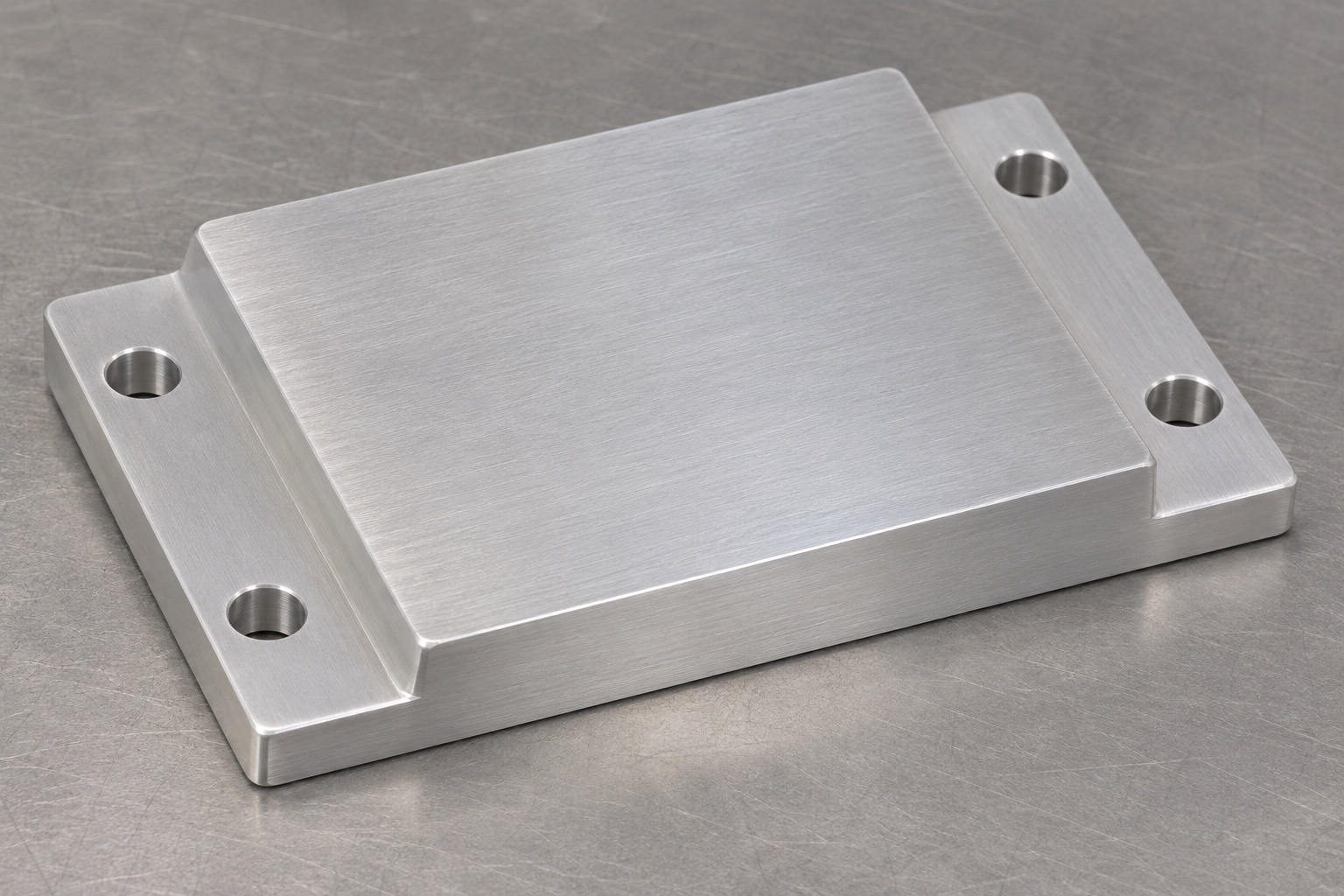
Start with the heat path
A heat spreader inside portable ultrasound equipment connects a local heat source to a larger conducting surface. The plate is only one element in a path that includes the interface material, supporting structure and the way heat ultimately leaves the enclosure. A machined plate with a bright, flat face does not demonstrate adequate cooling. Identify both sides of the intended path before defining the plate: the electronics package that supplies heat and the structure that receives it. The equipment owner must verify temperatures, limits and system behavior on the intended assembly.

Describe the installed stack
Build a stack model using the electronics height, board position, support heights, spreader step and intended interface material. Use the mounted condition rather than the overall outside height of the plate. A hole pattern may line up while the contact gap remains wrong. Check the smallest and largest likely gaps, including geometric variation and assembly movement. When there are several heat sources at different heights, do not assume a single flat pad will contact all of them appropriately. Define which surface is expected to carry contact and which areas need clearance.
Separate the land from mounting ledges
A stepped spreader can have a raised contact land and two lower side ledges that carry its fasteners. The drawing should relate the height of the land to the surfaces that seat against the enclosure or standoffs. Identify the usable thermal contact area and keep edge radii, transition zones and clamp marks outside it as required. Side ledge thickness is a different feature from step height, and both can affect assembly. A well-defined drawing allows the supplier to correct one height without altering an unrelated surface or confusing the two.
Specify the interface material with its owner
A compliant interface material can fill a gap, but allowable thickness and compression depend on the selected product and the assembled structure. Consult the material manufacturer and the equipment owner about the intended gap range, pressure, handling and compatibility. Do not use pad thickness to cover an unspecified machining error. A material value measured under one test condition is not the thermal resistance of the device. If electrical isolation is required, define it separately and verify the intended stack rather than assuming that an aluminum finish or a generic pad provides it.
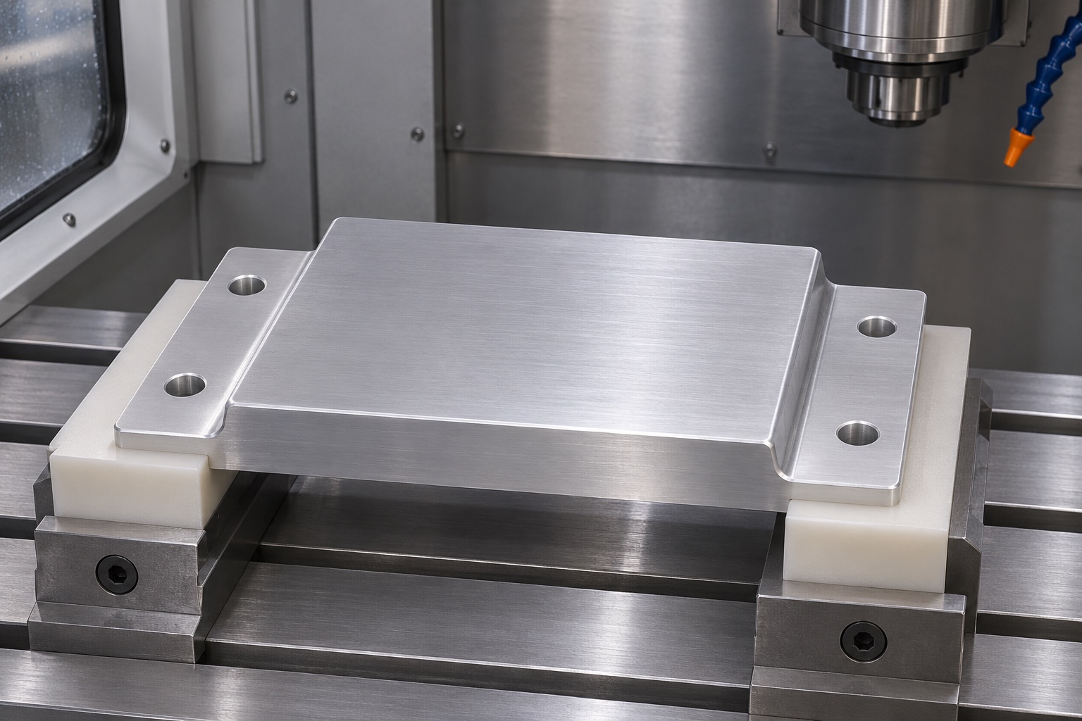
Plan machining around the reference plane
Choose a material and stock condition that the drawing allows, then establish the mounting reference on supported stock. Removing most of the material from one side or tightening thin side ledges can change the released shape. A candidate machining plan can include balanced stock removal, an intermediate release and a finish setup that supports the part without flattening it artificially. Evaluate the route against trial measurements rather than assuming one process sequence always works. The land must be reachable with a finishing tool without damaging the surrounding shoulders or mounting edges.
State the surface requirement in functional terms
Flatness describes how a surface lies between two parallel planes; it does not establish its height relative to another surface. Roughness and waviness describe other aspects of the surface. Use the requirements that the contact design needs, rather than specifying mirror polish because the surface transfers heat. If a coating or conversion treatment is needed, identify the zones that receive it and whether final measurements apply before or after treatment. Unapproved material removal or surface treatment can change the installed gap even when appearance seems to improve.
Check fastener and tool access
The mounting holes must clear fasteners in their actual installed positions. Check head clearance, washer contact, tool approach and nearby electronics. The clamp load should follow the mechanical design and the approved assembly procedure, not a suggestion from an illustrative image. Where ledges can flex, consider whether the installed contact pattern differs from the free-state map. Verify any bending or contact limits in the real assembly. Do not assume that a tighter screw improves thermal transfer; it can instead distort a plate, load a package or squeeze a compliant material beyond its intended condition.
Measure step height and form independently
Set the released part on the defined supports and establish the mounting plane according to the drawing. Record step height to the contact land at several locations, avoiding the blend. If a flatness requirement applies, collect enough points or a suitable scan to represent the intended functional area. Report form and relative height as separate results. Measurements taken while the part is held flat may not represent the state in which the instrument receives it. Document the probe strategy and support condition so the team can repeat a disputed result without changing the definition.
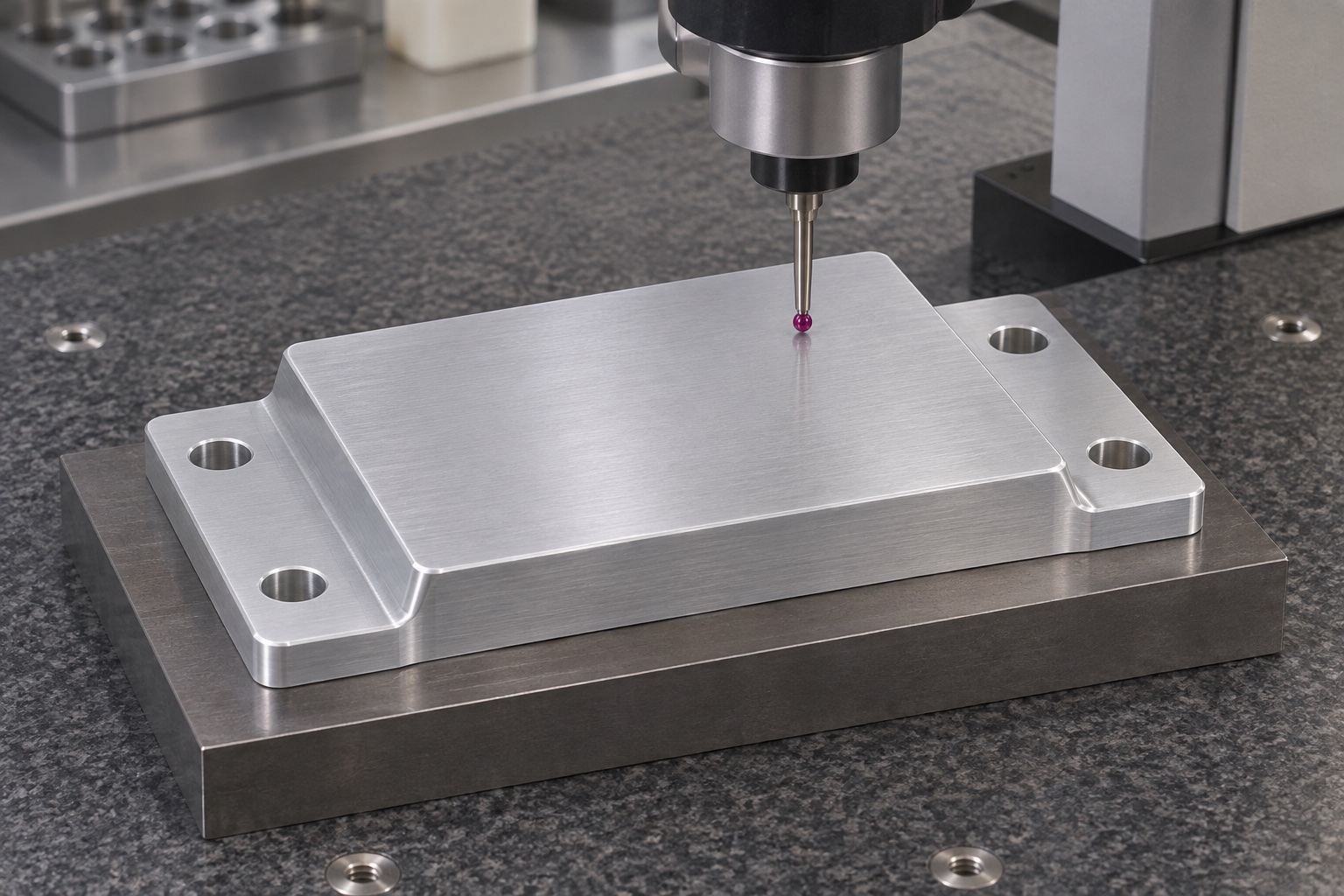
Verify the mechanical build before thermal testing
A trial assembly can examine clearances, permitted pad contact and accessibility while the electronics are unpowered and represented by an appropriate dummy if needed. Identify the drawing revision, interface material and assembly condition in the record. A visible witness mark can help explain seating but is not a measurement of thermal resistance. The equipment developer should decide whether a dimensional or mechanical discrepancy needs correction before powered tests. Use a separate test plan for the intended heat load, enclosure and operating conditions; the plate supplier's dimensional report does not replace that verification.
Protect contact faces from ordinary damage
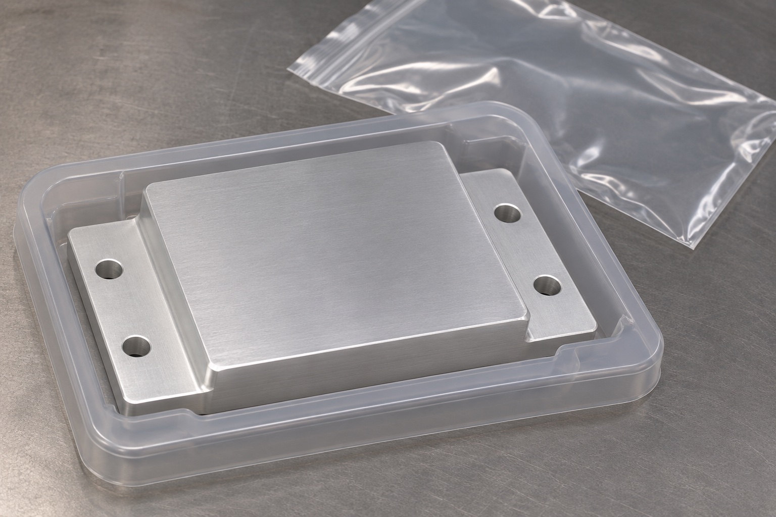
A handling plan should keep fingers, adhesive, sharp chips and metal separators off the contact land. A dent or raised edge can affect fit, even if it occupies only a small area of the part. Specify an approved cleaning and protection method and the condition expected at receipt. Where a temporary film is permitted, agree on its removal and residue criteria. Protective packaging is not evidence of cleanroom processing or sterility. For an internal electronics component, the focus here is on preserving the specified surface and preventing debris from entering the assembly.
Choose release evidence appropriate to the part
Ask for the drawing revision, material records, a feature-level report of the mounting faces and contact land, and the agreed surface and package checks. Where a required finish is performed externally, record which measurements are taken after it and ensure the finished geometry remains traceable. Do not report a temperature decrease, acoustic performance or device approval unless the actual system has been tested by the responsible team. The component report can support the wider validation program, but its purpose is narrower: confirm that the supplied plate meets its specified manufacturing requirements.
Provide the stack information with the quote
Share the model, locating scheme, material and finish requirements, and a drawing identifying the land and ledges. Include the permitted gap range and the state in which measurements are required, or tell the supplier explicitly that the equipment owner will establish those limits. Ask for proposed workholding, roughing and finishing plans where geometry is likely to move. Set acceptance expectations for packaging and receiving inspection. That information makes it possible to discuss manufacturing trade-offs without treating the plate's visible shape as a shortcut to thermal design or regulatory verification.
Manufacturer background reference: next.henkel-adhesives.com.
FAQ
Is this plate a heat sink by itself?
It is an example of a spreader in a larger heat path. Its job is to conduct heat to another part of the design. The complete enclosure, interfaces and heat rejection method determine whether the assembly meets its thermal limits.
Can a thicker gap pad fix an incorrect step height?
Not as an assumed substitution. Pad behavior depends on the actual product, gap and allowable compression. Ask the equipment owner to assess stack and contact conditions before changing the pad or machining the plate to another height.
Why specify land flatness and step height separately?
Flatness controls form on a surface, whereas step height relates one surface to a mounting reference. The first does not determine the second. Report the approved features and reference condition separately rather than inferring fit from a single reading.
Should the land be polished to a mirror finish?
Only if the approved design specifies it. Useful surface requirements depend on the interface and the assembly. Uncontrolled polishing can remove material, round edges or change the gap. Specify measurable form and finish conditions rather than appearance alone.
Does a dimensional report confirm a temperature reduction?
No. It verifies part geometry against a drawing. Temperature depends on the full assembly, operating state, environment and test method. The equipment team should define and document thermal verification separately for the intended ultrasound instrument.
What should be protected in transit?
Protect the broad contact land, mounting faces and edges from impacts and residue. An individual pocket that supports noncritical surfaces is one option. Agree on the protective material and cleanliness requirements; the example does not represent sterile delivery.

tanghangyun@oemach.com