
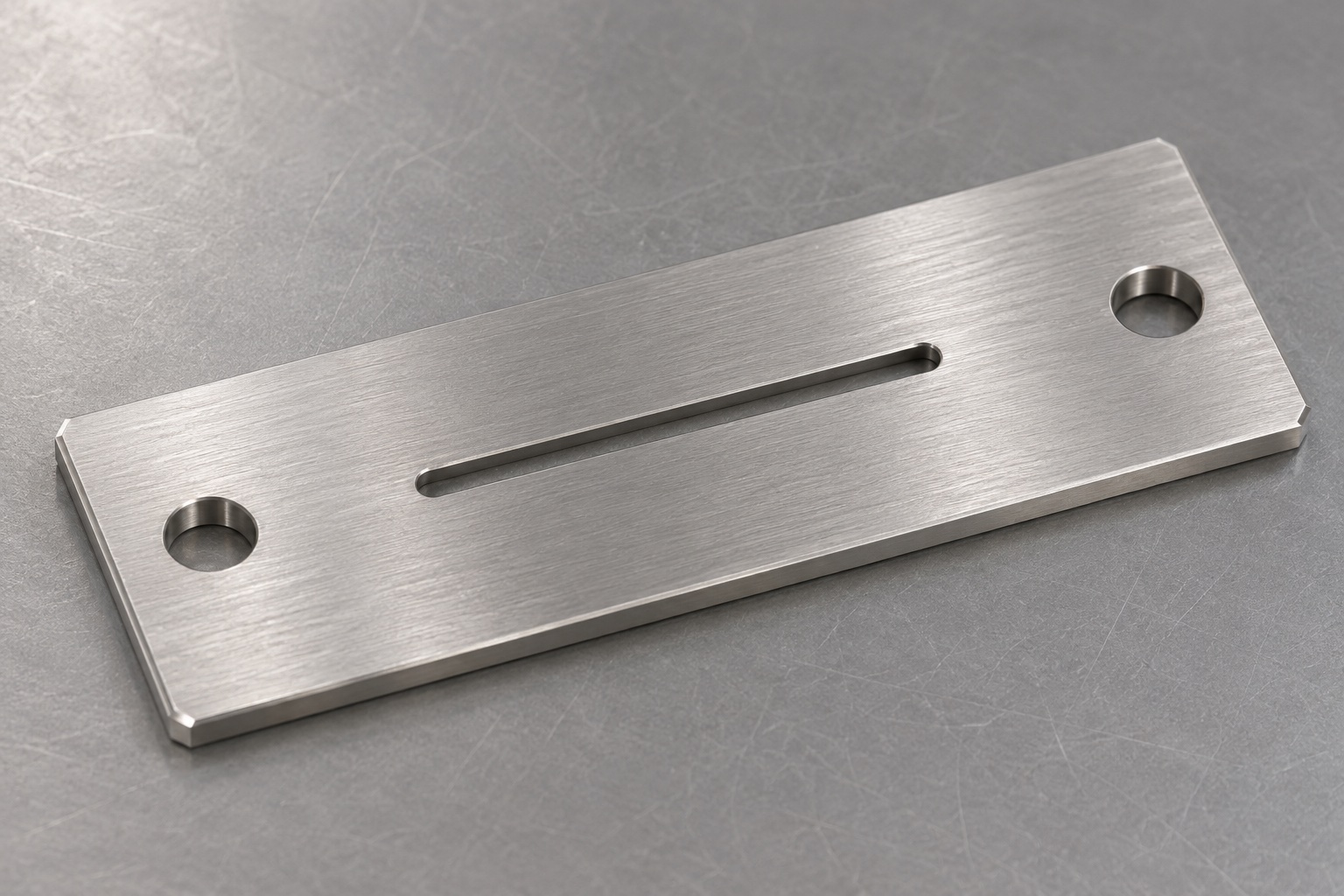
Name the actual aperture function
A slit plate used inside a diagnostic photometer is a mechanical aperture, not a calibrated measurement instrument. Its opening may define a light path, but the optical consequence of changing that opening depends on the rest of the instrument. A design review should identify the slit plane, direction of illumination and allowed installation orientation. Describe whether the aperture is intended to limit a beam, suppress unwanted paths or establish a defined field. That distinction tells the machining supplier which edges control the useful opening and which are merely clearance.

Specify the opening as a profile
Width alone is not enough for a long narrow opening. Define the usable length, both end transitions, straightness of the long edges and the relationship of the slit centerline to the mounting references. Give the inspection team the stations where width should be sampled and explain whether end transitions are excluded. If the width is evaluated on a particular face, name it. If the intended opening is a silhouette through the thickness, define that condition instead. These are different requirements when taper, edge radius or finish changes the apparent boundary.
Separate optical and mechanical datums
The plate may seat against a support plane while fasteners pass through holes that allow assembly clearance. An optical axis defined by the equipment is not necessarily identical to the midpoint between those holes. Relate the opening to the surfaces or locating features that actually position it in the assembled instrument. If rotation is critical, identify the reference that fixes it. An opening can have a good width yet be displaced or tilted relative to the installed beam. Keep placement and size checks separate so a supplier knows which variable needs correction.
Choose a process that can make the edge
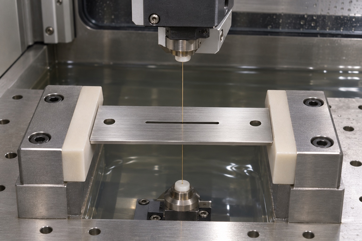
A narrow through slit in conductive stainless steel can be a candidate for wire electrical discharge machining. Feasibility depends on wire access, the minimum feature size and the allowed end geometry, not merely on the fact that the part is conductive. For a closed opening, discuss where the wire can be threaded and how the internal cutout is managed. Compare that plan with milling or another route against the drawing. The process illustration does not establish a particular machine capability, tolerance or a production-approved cutting sequence.
Account for the thin blank
A thin plate can change shape when material is removed or the fixture is released. During planning, identify where supports can touch without scratching the reference face or blocking wire access. A flat reading taken under clamp pressure is not evidence that the released plate sits flat in its mount. Consider how the blank is prepared and how its finished outline is handled during the opening operation. If the drawing specifies a restrained assembly condition, describe the restraint in the inspection instructions instead of silently changing the state in which the part is measured.
Keep surface requirements distinct
A bright brushed face can be easy to inspect, but its appearance is not a specification for optical absorption or stray-light behavior. If an instrument requires a matte surface, an approved coating or restricted reflectance, the design owner should define the treatment and its acceptance method. Coatings and edge finishing may alter the useful opening. State whether the slit is accepted before or after the final surface process. Do not choose a surface treatment solely because it looks darker in a rendering, and do not infer optical performance from the alloy designation.
Control the edges without widening the slit
Create separate edge notes for the handling perimeter, mounting holes and optical opening. A blanket deburring note can lead to excessive rounding of the slit while leaving an unwanted feature on a critical face. Agree on an edge treatment that removes loose material without shifting the specified profile. If a controlled edge break is allowed, define how it relates to the measured opening. Where the chosen process leaves a surface layer or texture of concern, resolve the acceptance and any follow-up operation with engineering rather than assuming a skim pass resolves every issue.
Use repeatable illumination and focus
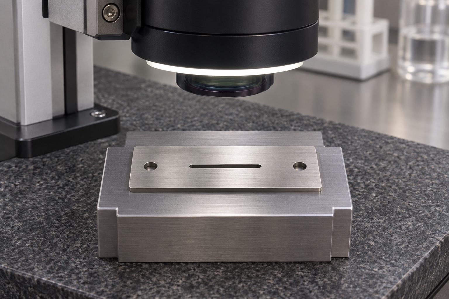
Backlighting is useful for creating a silhouette through a slot; reflected light can help inspect a named surface edge. Choose illumination based on the boundary the drawing actually defines. Record magnification, focus plane, orientation and edge-selection settings so a repeat measurement can be compared fairly. An inspection image with high contrast is not necessarily dimensionally accurate. Calibrate the system for the work area and verify that its resolution and uncertainty are appropriate for the tolerance. Avoid manually selecting a favorable edge when the approved recipe detects another one.
Check both faces when taper matters
When a slit has appreciable thickness, a single projected image may combine or obscure the two face boundaries. If the drawing requires width at each face or restricts taper, use a method that can distinguish those features and record which side was viewed. Sample multiple stations along the straight edges to detect local narrowing or variation. A spreadsheet containing one average width can hide an obstruction that matters to the beam. Preserve the measured locations in the report so any discrepancy can be traced to a particular section of the opening.
Tie the inspection back to installation
A first article review should include the mounting face condition, aperture profile and position, hole clearance and the approved installation orientation. A surrogate mount can identify binding, movement or a plate installed backward. It cannot establish spectral response, detector linearity or assay accuracy. The equipment developer must define functional tests for the assembled instrument using its intended optics and operating conditions. If dimensional evidence and a system test disagree, do not change the slit based on a single reading; first check datums, fixture condition and the test configuration.
Protect the aperture through handling
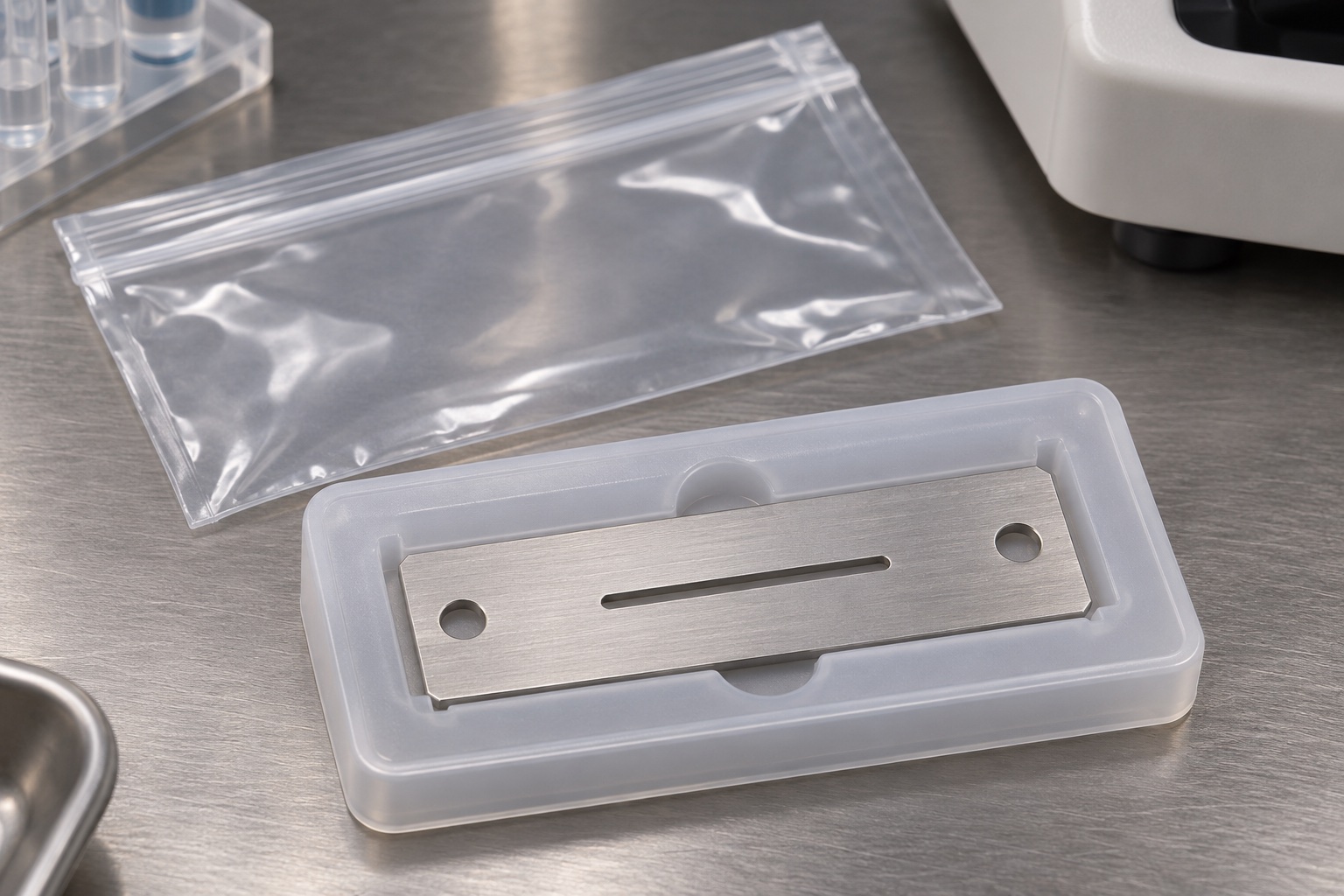
Place the plate in a pocket that prevents contact between the slit edge and adjacent hardware. Avoid pushing tissue, foam or an adhesive liner into the opening. Handling instructions should distinguish clean protective packing from sterilization and identify which surfaces must remain free of fingerprints or residues. Discuss an approved cleaning method if an optical surface requires it. Label the revision on the package rather than on a face that will be mounted or illuminated. A clean-looking photo does not verify a numerical cleanliness level or shelf life.
Give suppliers a complete RFQ
Supply the plate model, revision, alloy and finish, the true optical profile and its datum scheme. Include the intended inspection face or silhouette definition, usable width stations and any restrictions on taper or edge condition. Identify planned functional tests separately so the quote does not imply that a dimensional report certifies instrument behavior. Ask how the supplier would manage threading access, part support and protection of the aperture. The best deliverable is a part and evidence that match a specific drawing, not a generic precision label or an unsupported performance number.
Manufacturer background reference: www.makino.com.
FAQ
Can a smaller slit guarantee higher instrument resolution?
No. Slit geometry can influence an optical system, but the result depends on the illumination, optics, detector and assembly. A machining report confirms specified part features only; validate the intended resolution or other performance with the complete instrument.
Why might a drawing identify one measurement face?
The two boundaries can differ if there is taper, an edge break or a finish buildup. Naming the face lets the machinist and inspector measure the same feature. A through silhouette is a valid alternative only when that is what the design requires.
Is wire EDM always the right process?
No. It is one option for a conductive plate with a through opening. Review wire threading, cutting access, permissible corner shape, edge requirements and cost before selecting it. Use trial and inspection evidence to confirm the chosen route.
Does a single slit width establish the aperture profile?
No. Width at one station can miss bowed edges, a displaced centerline or a restriction near an end. The drawing and inspection plan should define multiple stations or a profile method tied to the functional references.
What is the purpose of backlighting?
It makes the silhouette of a through feature easier to identify. It does not by itself show which face controls the opening or validate the measurement. Define the edge convention, calibrate the system and use repeatable settings.
How should a slit plate be protected?
Use physical separation and a pocket that supports the plate outside the useful aperture. Avoid abrasive inserts and adhesive on functional faces. Specify any additional cleaning and packing requirements separately; protective packaging alone is not a sterile delivery.

tanghangyun@oemach.com