
The example and its boundaries
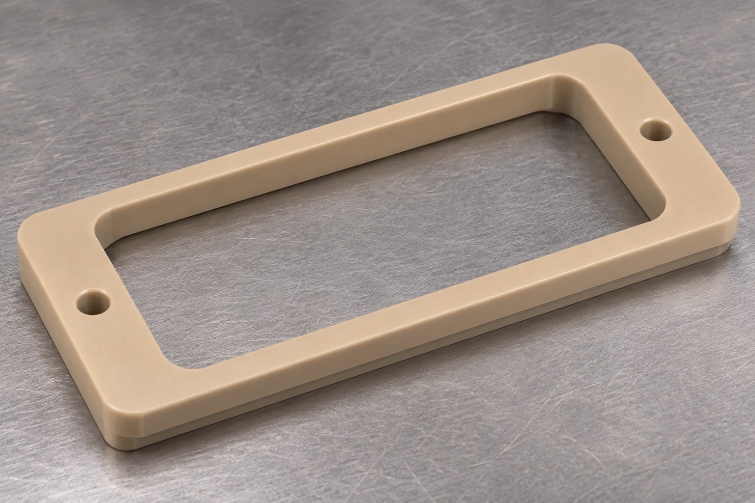
This representative machining example concerns a natural PEEK perimeter keeper for a benchtop diagnostic instrument. No customer order, test result or device approval is claimed. The concept uses a rectangular open window, two plain end mounting holes and a shallow underside ledge to retain the dry flange of a cartridge. The keeper is not a wetted manifold or a disposable fluid path. Its intended job in the example is limited to keeping a cartridge flange within the mechanical envelope defined by a separate seat and mounting assembly.

Translate the assembly concept into features
A flat face rests against the equipment mounting structure. The central window clears the body of the cartridge, while the underside ledge is the candidate contact band for its flange. The two end holes admit fasteners without being treated as precision pins. The equipment seat, rather than the keeper, controls the illustrative cartridge's lateral location. That distribution of roles determines what belongs on the first article report: the opening and ledge relative to the mounting face, and the hole pattern as a separate assembly clearance check.
Review the corner conflict first
The likely design question is whether the cartridge's largest corner can pass the keeper's smallest effective internal opening. The team would overlay the limiting profiles at the actual approach angle, rather than infer clearance from nominal width. Any revision to the corner should be reflected in the model and drawing before machining. A larger relief can simplify tool access, but only the design owner can decide whether it reduces the retaining band too far. Illustrations show rounded corners for communication; they are not dimensional drawings and do not establish an approved mating fit.
Choose and trace the stock
The scenario assumes unfilled natural PEEK from a documented lot. A purchasing specification would identify the grade, stock form and any conditioning requirements needed for consistent machining. Before setting up the part, the shop would compare incoming stock thickness and form with available machining allowance. Substituting a filled or differently processed grade would require review, since the material can respond differently to cutting and handling. No statement about color, traceability paperwork or stock origin should be interpreted as a claim that this concept is approved for clinical or reagent contact.
Develop a support and release sequence
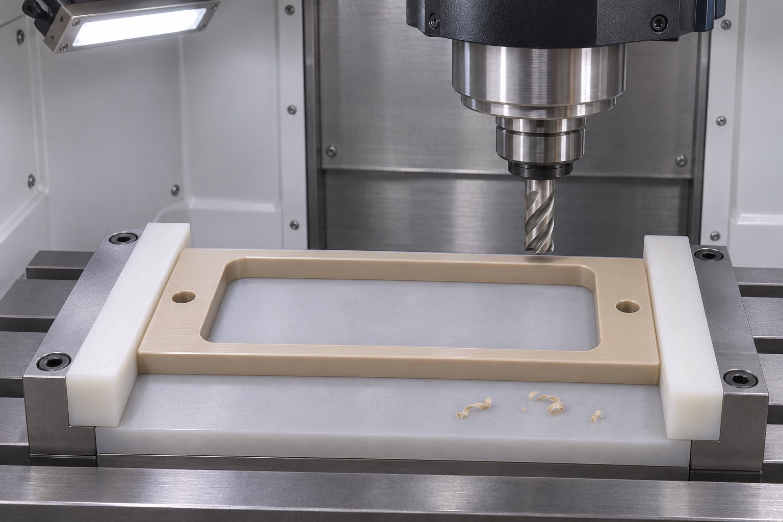
One candidate sequence is to establish the reference faces while the blank is well supported, rough the central opening while retaining sufficient stiffness, then finish the edges and ledge on broad supports. A planned release after roughing lets the operator look for movement before completing the functional surfaces. The machinist would select the sequence after trial work; the illustration does not prescribe feeds, speeds or cutter dimensions. Soft contact surfaces can reduce marking, but clamping still needs to be low enough that the thin sides are not pushed into a misleadingly square shape.
Produce the ledge and through holes
The underside ledge needs a consistent useful band, not just a nominal recess depth. A finishing pass would leave the corner blend outside the contact region indicated by the drawing. The end holes can be machined in a supported state with exit protection appropriate to the chosen process. Avoid blending their exits into the step, which could create a locally reduced section. Before removing the piece, the operator would compare visible edges with the feature plan and record any observed chip buildup or variation that could affect the next setup.
Distinguish the two inspection states
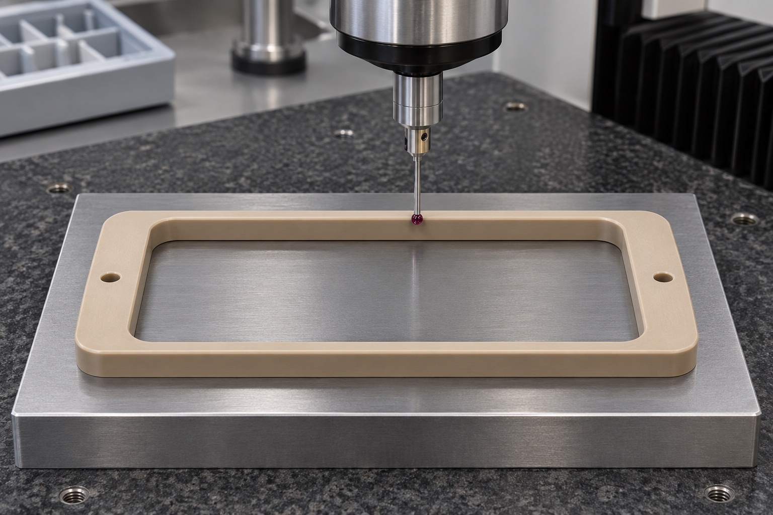
The inspection plan would record whether a value was collected on process supports or on the released keeper. A clamped width may help track a cutter, but it cannot show the final free-state opening. For the released check, the frame would rest on prescribed supports without weights pushing the webs down. Record the condition, measured features and gage method with the part identifier. This example deliberately does not assign a numerical tolerance or measured result; those depend on the cartridge envelope, the actual drawing and a demonstrated measurement process.
Set up a useful first article report
A proposed report would identify the mounting face, useful ledge depth at named stations, opening profile, corner radii, hole centers and local edge condition. For depth readings, confirm that the stylus reaches the contact band without hitting the adjacent wall. A low-force approach or vision method can be considered for narrow polymer features. Report which locations were inaccessible and resolve them through a method review, not by substituting a nearby convenient dimension. Any drawing ambiguity about the released form needs resolution before a production lot is accepted.
Review the fit without live reagents
A rigid, clean surrogate with documented flange geometry is a practical way to examine mechanical seating at the build review. In this scenario it would be inserted and removed using the intended access path, with the keeper mounted under the specified conditions. The inspection team would log whether the surrogate catches at the radius or leaves a mark outside the allowed contact band. These observations would not verify fluid containment, instrument accuracy or long-term life. A real validation plan would need the complete assembly and its defined operating conditions.
Control cleaning and edge work
After machining, the candidate traveler would call for inspection of the window corners, recess transition and both hole exits. Remove loose material without rounding the defined seating step or scratching the contact band. A compatible cleaning method would be agreed with the equipment owner, and the lot would be handled in accordance with that specified level. Visual absence of debris does not establish a quantified particle limit. If such a limit matters, define the sample, test method and acceptance criteria rather than making a cleanliness claim from an illustrative image.
Ship with mechanical protection
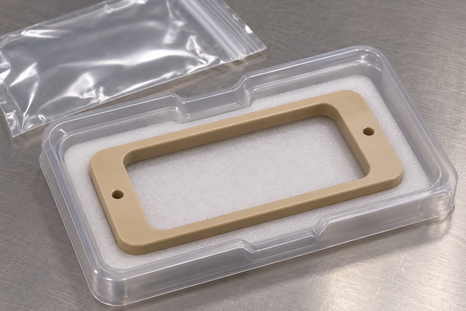
Each keeper can be supported in an individual nonsterile protective pocket that does not force its sides inward. The pack must allow removal without catching the shallow ledge. Place labels outside the bag or on agreed areas, not on the flange contact surfaces. Trace the packaged part back to the drawing revision and lot. The packaging illustration shows physical separation only; no particular cleanliness classification, sterilization process or validation is inferred. The receiving team should inspect for handling damage before using the frame in an engineering build.
Evidence requested for a real project
To turn the scenario into a release, request a signed-off drawing, material records, agreed edge and cleaning criteria, a first-article dimensional report and a documented assembly check. Close each discrepancy against a specific requirement. If the measured part fits the surrogate but disagrees with the drawing, engineering should resolve the discrepancy explicitly instead of relying on a convenient fit. The example illustrates how a clear dry-side boundary keeps the machining scope practical and keeps clinical, assay and sealing claims outside the manufacturing evidence.
Manufacturer background reference: www.ensingerplastics.com.
FAQ
Was this frame delivered to a customer?
No. It is a representative machining example. The geometry and inspection steps illustrate the type of engineering decisions involved, and the pictures are illustrative. No customer, completed delivery, numerical result or qualification is being represented.
Why use an open perimeter design?
It lets the drawing retain a defined external flange while leaving the cartridge body unobstructed. The opening does not by itself ensure access to ports or optics, so the contact map and limiting mating profiles still have to be checked.
Are the mounting holes threaded?
No. The example uses two plain clearance holes, one on each short end. Their function is fastener access rather than locating the cartridge. A real drawing would specify how the assembly locates and whether different hole features are needed.
Which dimension is most useful to check first?
Start with the mechanical relationship that controls seating: the underside ledge relative to the installed reference face and the mating flange. Check opening profile and corner clearance as well; one depth or one width cannot establish complete fit.
How would a distorted trial frame be handled?
Record the released condition on defined supports and compare it with the drawing. Review the stock and clamp sequence before changing the nominal geometry. Do not force the frame flat for final acceptance unless the drawing explicitly specifies a restrained inspection state.
Is the packaged part sterile?
No sterile delivery is represented. A protective tray or bag only describes handling protection in this scenario. Any controlled cleanliness requirement, test method or sterile packaging specification must be defined and verified independently for the actual application.

tanghangyun@oemach.com