
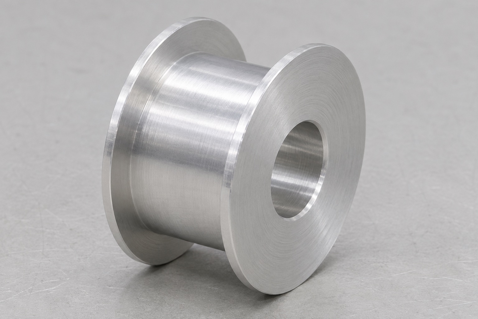
Define the component before discussing the drive
A smooth idler pulley can be part of the mechanical transport arrangement inside a medical analyzer. This guide concerns the machined pulley body, not a complete belt drive or an approved medical device. The illustrative component has two circular flanges, a smaller smooth cylindrical belt-contact barrel and one concentric through bore. There are no timing teeth, installed bearings or fastening screws. Begin the manufacturing discussion with the actual belt specification, mounting arrangement and controlled drawing. A photograph alone cannot establish whether the pulley is suitable for the intended analyzer mechanism.

Identify the belt surface that will meet the barrel
The equipment designer should identify which face of the belt contacts the smooth barrel and whether motion reverses. Do not assume a smooth pulley can replace a toothed drive pulley. The belt supplier's guidance belongs in the system design review, together with the proposed path and installation access. For machining, the useful outputs are a defined barrel profile, usable contact width and clearly identified edge transitions. These requirements should be stated independently of the flange outside diameter, which does not describe the contact surface or the installed belt clearance.
Choose a bore-based reference scheme
If the bore establishes the installed rotation axis, identify that relationship on the drawing and make the inspection setup reproduce it. The designer should specify the bore limits, any form requirement and the face that locates the pulley axially. A mandrel used for inspection must be appropriate to the actual bore and its permitted fit; an arbitrary shaft is not an interchangeable datum simulator. Record whether the inspection checks the barrel relative to the bore or only checks the barrel in the manufacturing chuck. These are different conditions and can give different information.
Separate flange spacing from overall width
Overall width includes both flanges, while the clear span between their inner faces describes the space available around the belt. Both dimensions may matter, but neither should silently substitute for the other. Define which surfaces are to be measured and whether edge radii or chamfers reduce the usable width. Establish how the pulley sits beside washers, spacers or nearby guards without inventing an assembly stack from the image. A drawing review should also distinguish a parallel-sided smooth barrel from any deliberately crowned profile; the illustrated concept uses a straight cylindrical barrel.
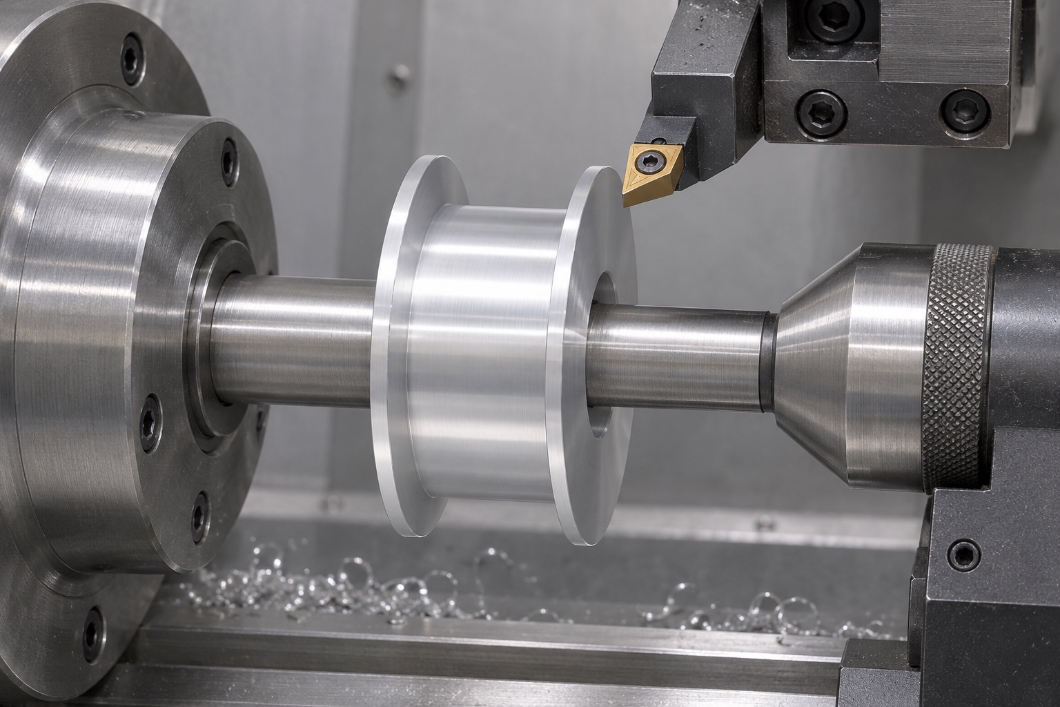
Review stock and turning sequence together
For a 6061 aluminum concept, confirm the alloy condition, source identification and any specified finishing route before selecting stock. A turning plan would consider how the bore, barrel and locating face can be related while controlling the thin flange features. Roughing and finishing are separate planning decisions, not proof of a particular dimensional result. Workholding should support the part without relying on a flange edge that could be marked or displaced. If a second setup is needed, identify its locating surfaces and the checks needed to preserve the intended relationship between features.
Keep the belt-contact surface free of accidental features
The contact barrel should be reviewed for unintended steps, tool marks, sharp transitions and embedded debris against the approved finish requirements. Do not prescribe a numerical roughness merely because the part appears polished in a generated image. Finishing operations must preserve the specified diameter and profile rather than rounding the whole part indiscriminately. If a coating is proposed, state which dimensions apply before or after coating and whether the bore is masked. A coating decision also needs compatibility review for the actual belt and cleaning conditions; appearance is not a substitute for that review.
Plan bore and width measurements explicitly
A bore measurement plan should identify the instrument, measurement positions and the feature being accepted. A single diameter reading does not characterize every possible form issue. Flange spacing may require access that a general outside measurement cannot provide, so choose the method before production rather than after the part reaches inspection. Establish the temperature and handling conditions relevant to the agreed limits. Keep the report tied to the drawing revision and individual feature identifiers, with instrument records available where required. No measured dimension or acceptance result is claimed in this illustrative discussion.
Describe runout as a setup-dependent measurement
Where the drawing requires runout, specify the referenced axis, the checked surface and the method of supporting and rotating the pulley. Radial observation at the barrel and axial observation at a flange face are not the same measurement. The contact point, seating condition and freedom from debris all affect how the observation should be interpreted. A dial indicator next to a pulley is only an illustration until the actual setup, limits and recorded readings are defined. Do not convert a favorable hand rotation into a claim of drive accuracy, dynamic balance or analyzer positioning performance.
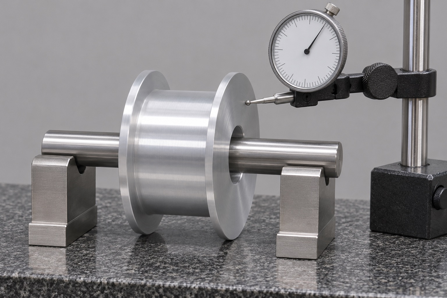
Remove burrs without changing the interface
Burr review should include both bore entrances, the barrel-to-flange transitions and the outside flange edges. Define the intended edge condition so the operator does not enlarge a locating chamfer or thin an already narrow flange while trying to make the part feel smooth. Cleaning should remove machining chips and process residues using an approved, compatible procedure. Inspect the part again after cleaning, especially where a bore edge can retain a loose fragment. A visually tidy surface is not evidence of particle-count compliance, sterility, biocompatibility or suitability for direct patient or sample contact.
Keep assembly observations separate from acceptance
An agreed nonclinical development check may examine whether identified mating parts seat, turn and clear nearby structures. Record the belt, bearing or shaft versions actually used, together with any spacers and mounting hardware. That observation complements dimensional inspection but does not replace it. Belt tracking, loading, operating speed, wear and complete equipment safety remain system questions requiring the appropriate design evaluation. If interference appears, investigate the drawing and assembly references before modifying the flange by hand. Approved changes should return to the controlled manufacturing and inspection documents, not remain only on a development sample.
Protect flanges and bores during handling
Separate individual pulleys so flange edges cannot strike other metal components during transport. Select packaging that supports the body without forcing a thin edge against a hard pocket. Protect the bore from loose foam fragments and from identification labels placed on functional surfaces. The agreed packaging description should distinguish clean protective packaging from any validated sterile barrier or cleanroom process. Include the part revision, quantity and material traceability references outside the protected functional surfaces. An opened bag in a representative image explains handling intent; it does not establish that a particular cleanliness classification has been achieved.
Build an RFQ around the controlled interfaces
A useful inquiry includes the model and drawing revision, belt-contact description, bore fit, flange clearance, material condition, finish requirements and the features requiring inspection records. State the expected quantity and any permitted production alternatives without implying that a change of manufacturing route can alter the drawing. Identify required certificates or packaging evidence as requested deliverables, not as existing capabilities assumed from this article. The result should be a reviewable manufacturing proposal that keeps component dimensions separate from the performance of the complete analyzer. The images here remain illustrative and contain no customer delivery or test results.
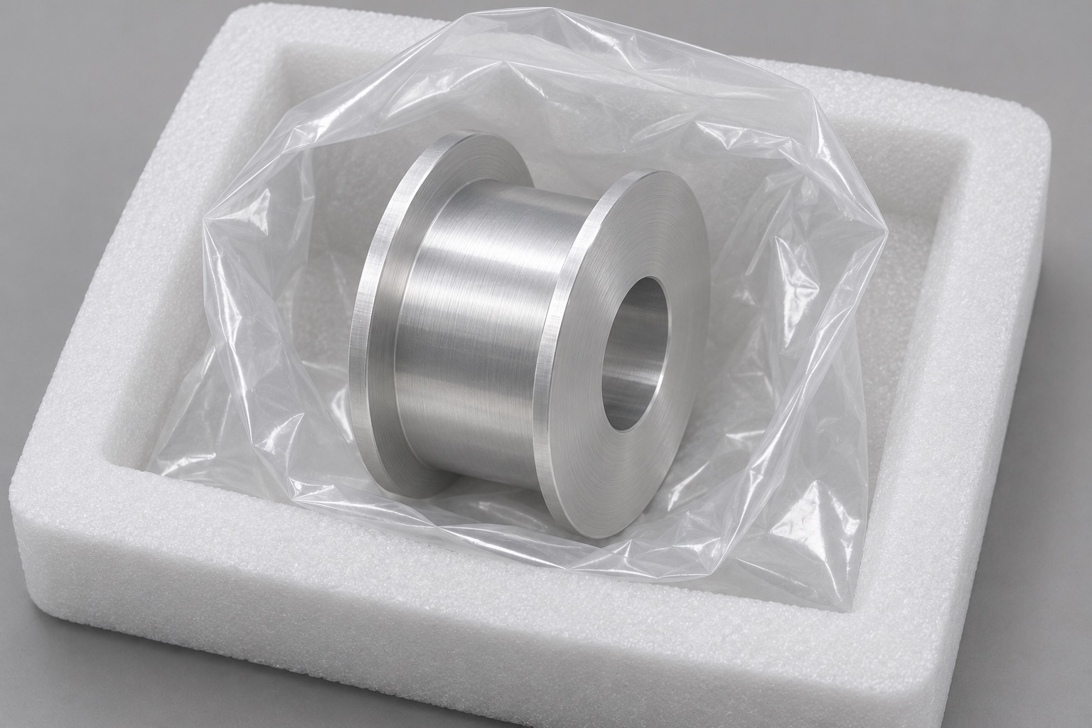
Manufacturer background reference: www.gates.com.
FAQ
Is this a toothed timing pulley?
No. The illustrated component has a smooth cylindrical barrel and two flanges. Belt selection and the permitted contact face must be established by the equipment designer; a smooth idler must not be treated as a substitute for a toothed drive pulley.
Does the illustrated bore contain a bearing?
No bearing is installed or specified in the concept. The drawing must define the actual bore interface and any bearing, shaft or spacer arrangement. Those components cannot be inferred from a plain through bore or from a manufacturing illustration.
Which width controls belt clearance?
The clear distance between the inner flange faces is distinct from total outside width. The drawing should identify usable contact width and relevant transitions. The actual belt and assembly stack determine which clearances need acceptance limits.
Does an indicator picture prove acceptable runout?
No. Runout acceptance requires a defined datum simulation, checked surface, support arrangement, instrument and recorded readings against approved limits. The illustration contains no measured result and does not establish dynamic balance or motion accuracy.
Can the pulley be assumed suitable for sterilization?
No sterilization compatibility or sterile condition is claimed. The chosen alloy, finish, cleaning process and intended equipment use need their own review. Protective packaging alone is not a validated sterile barrier or evidence of medical-device compliance.
What information should accompany an inquiry?
Provide the controlled drawing, model, quantity, material condition, bore interface, flange clearance, finish and required inspection documentation. Add the actual belt-contact arrangement and packaging needs so quotation and technical review address the intended interfaces rather than appearance alone.

tanghangyun@oemach.com