
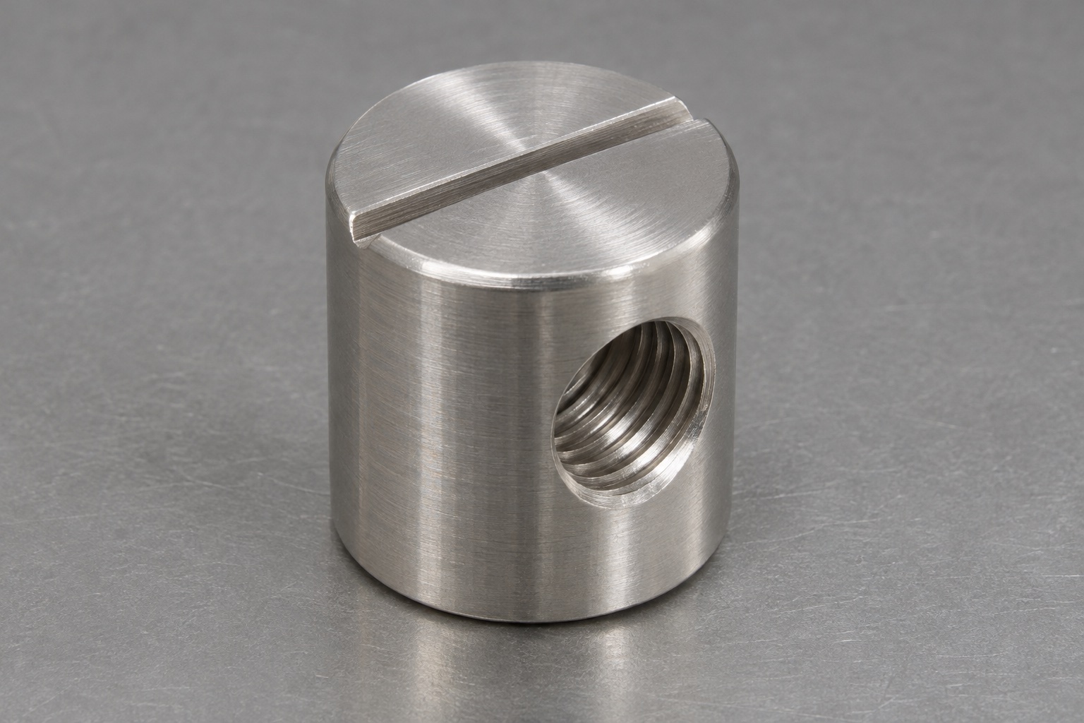
Define the transverse fastener concept
An internal medical equipment service-panel joint may require a custom cylindrical nut when the bolt and receiving-barrel directions differ. The concept here is a short 316L barrel with one female threaded hole through its curved side and a straight alignment slot across one otherwise solid circular end. The thread axis is transverse to the barrel axis, not an axial bore. No bolt or mating panel is included. This is an illustrative mechanical interface, not a rated medical fastener. The designer must define the housing, bolt, access and load path before manufacturing release.

Distinguish the barrel fit from thread engagement
The outer cylinder fits into a receiving feature, while the transverse thread engages a separate bolt. These are different interfaces with different requirements. State whether the receiving hole provides clearance, location or another approved contact. Do not assume a press fit simply because the part resembles a dowel. Review how the barrel is retained before the bolt is installed and how it can be removed for service. An accepted outside diameter does not establish usable thread engagement or the complete joint's ability to remain secure in medical equipment.
Locate the side hole from usable references
Define the transverse hole's position along the barrel, its relationship to the cylinder axis and the relevant end reference. Specify any required orientation relationship between that hole and the alignment slot. A perspective image does not communicate these relationships reliably. If the slot is intended to indicate thread direction during assembly, that function must be controlled by the actual drawing. Do not assume every commercial cross dowel uses the same convention. A symmetric cylindrical surface alone cannot tell an assembler which way the internal thread faces once the barrel is hidden.
Specify the complete female thread
Identify thread system, nominal size, pitch, hand, fit and the usable threaded region. Review the curved entries and any permitted chamfers or runout. The visible opening on a cylindrical wall does not by itself identify full engagement available to the bolt. The bolt's length and approach path must be reviewed with the actual housing. Do not count clearance spaces or incomplete entry threads as effective engagement without a defined basis. Appropriate thread inspection addresses its specified scope; it does not independently prove joint strength, resistance to loosening or safe service behavior.
Define the alignment slot as a separate feature
State slot width, depth, length and relationship to the controlled thread orientation. Confirm screwdriver access in the assembly and enough remaining material beneath the slot. The slot is an orientation aid, not an authorization to tighten the complete joint through an arbitrary screwdriver torque. No cross recess, hexagon or axial threaded hole is included in the concept. If the assembly needs a different drive or retaining feature, release that geometry explicitly. Do not deepen a slot merely because a convenient screwdriver does not match the approved interface.
Review wall sections and mating clearances
The transverse thread, external cylinder and end slot compete for available material. Review their combined geometry rather than checking each feature in isolation. The actual designer must assess remaining sections and the complete load path for the application. No universal wall thickness or load rating is supplied here. Check that the bolt can approach the thread without bottoming against an unintended surface and that the barrel can be oriented before enclosure. A successful hand assembly can reveal some interference, but it cannot replace the engineering assessment of the real joint.
Specify 316L and the delivered surface condition
Request the required 316L specification, stock form and traceability documentation. A stainless appearance does not identify a grade or condition. State any ordered passivation, polishing or other treatment and the final acceptance condition. Fastenright's cross-dowel information provides general interface context; a custom medical equipment concept does not inherit a catalog product's materials, availability, conformity or capacity. The application team must separately review cleaning exposure and any relevant medical requirements. Neither the alloy name nor a clean-looking surface establishes validated cleanability, biological suitability or sterile delivery.
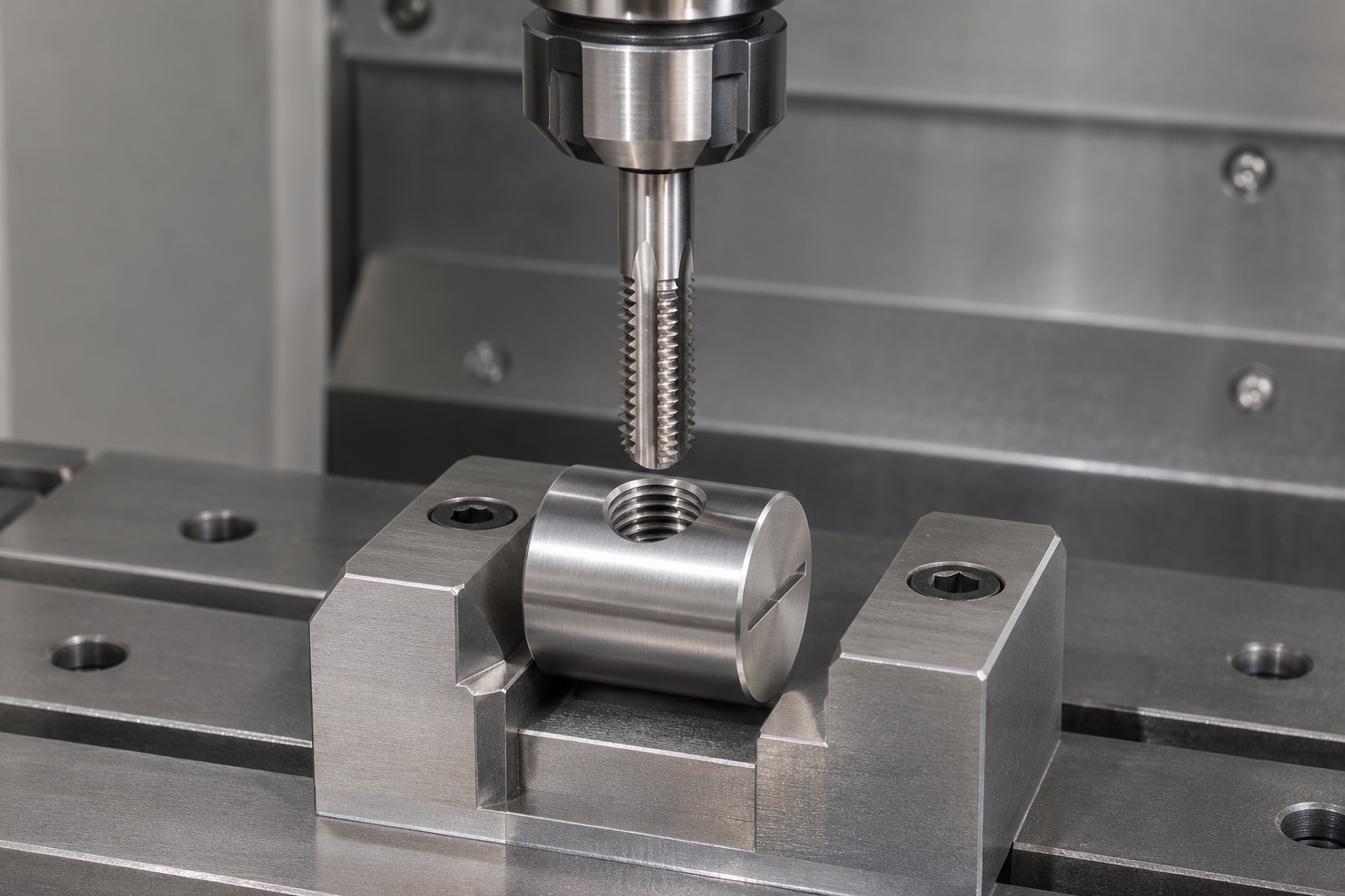
Plan turning and transverse machining together
A proposed route may turn the cylindrical body and ends, then establish the side hole, thread and alignment slot in appropriate fixtures. Preserve the agreed positional and orientation references through these operations. Support should prevent unwanted movement while leaving tool access to the curved entry. Protect finished external contacts during later setups. Exact tool selection, cutting conditions and stock allowance depend on the released dimensions and equipment. Do not add a center hole, an axial thread or a different slot simply because it makes workholding easier. The delivered geometry must remain the approved component.
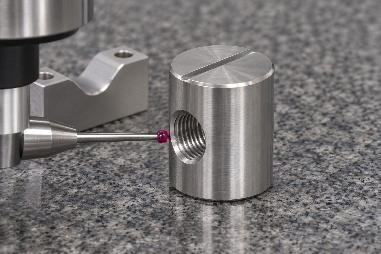
Inspect both interfaces and their relationship
The inspection plan should address outer diameter, length, transverse thread, hole location and the alignment slot according to the drawing. Select methods for the actual access and uncertainty requirements. Thread gauging alone does not establish where the thread lies relative to the barrel or how the slot indicates its direction. Similarly, a cylinder-size measurement does not verify the usable internal thread. Record support, orientation and sampled characteristics so results can be understood by another reviewer. A real report needs actual measurements and acceptance decisions rather than a statement that a bolt appeared to fit.
Deburr the curved entries without altering the thread
Review both side openings, slot edges and circular-end transitions for attached material. Define entry treatment so that burr removal does not erase required thread or change the approved bearing regions. A curved surface can make an entry burr less obvious from one viewing direction, so inspect with suitable access. Do not chase or polish an internal thread to hide a nonconformance. Authorized rework should be documented and rechecked. Cleaning is a defined component process; visual shine is not evidence of a measured particle level, validated disinfection or a medically qualified fastening assembly.
Bound assembly observations and protect the component
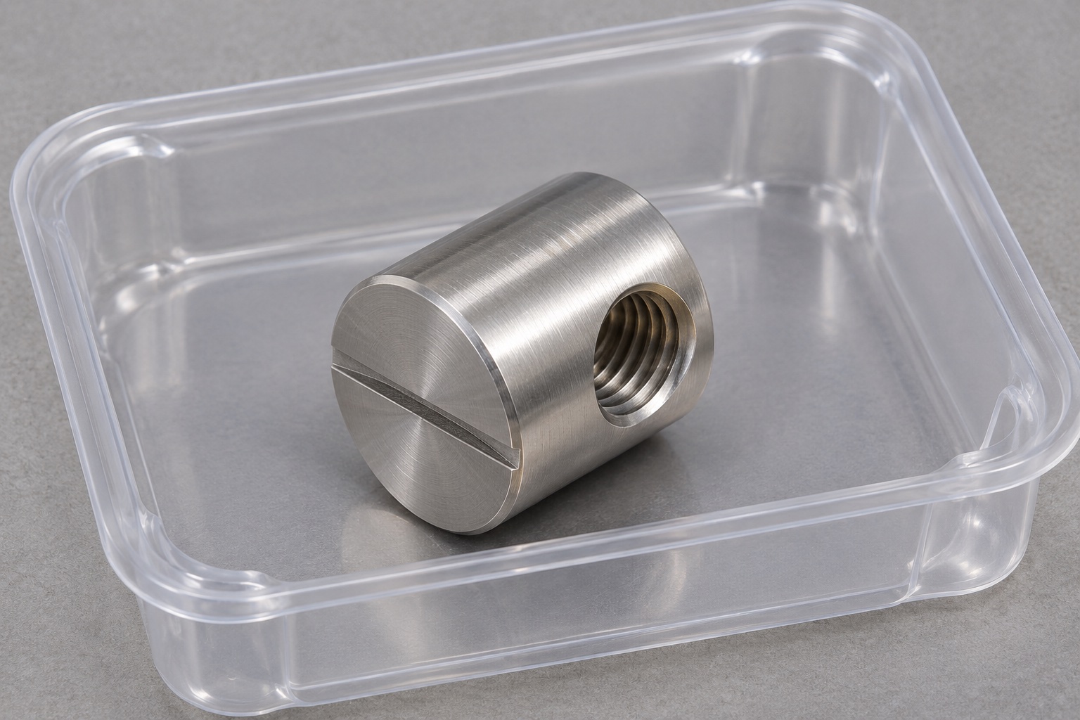
An agreed trial can observe barrel orientation, bolt access and seating with identified mating parts. It should record the procedure without inventing an assembly torque or capacity result. Favorable hand installation does not establish preload, fatigue resistance, locking stability or safe retention in the complete equipment. Those need a relevant joint assessment. Package each barrel so neighboring parts cannot damage the thread entries or slot. Preserve part number, revision, material identity and inspection status. Ordinary protective packaging is not sterile delivery, and an illustrative tray is not proof of an actual customer shipment.
Prepare a joint-specific manufacturing request
Provide the controlled model and drawing, receiving-hole definition, bolt specification and path, reference system, slot-orientation convention, material, finishing and inspection scope. Identify any separate retention method and service-access restrictions before release. Resolve incomplete thread or mating information rather than relying on the name cross dowel. A useful supplier discussion separates manufacture of the nut from verification of the complete medical equipment joint. No customer history, measured capacity or certification is implied by the example, and any repeat order should preserve approved revisions instead of depending on a manually altered assembly sample.
Manufacturer background reference: www.fastenright.com.
FAQ
Is the female thread axial or transverse?
It is transverse: the threaded hole passes through the curved side wall, perpendicular to the barrel axis in this concept. The circular end contains an alignment slot, not an axial threaded opening. A different arrangement would require an explicitly revised design.
Does the cylindrical body require a press fit?
Not automatically. The receiving-hole relationship must be specified for the actual housing and assembly. Clearance, location and retention are separate design questions. Do not infer interference from the name dowel or force the barrel into an undefined receiving feature.
Does the end slot always show the thread direction?
Only if the controlled design defines that relationship and the inspection plan checks it. Do not infer the convention from a photograph or another supplier's product. Define the reference and assembly access needed to orient the hidden threaded opening correctly.
Can a passing thread gauge prove joint capacity?
No. Gauging addresses specified thread characteristics within its scope. Capacity and retention depend on the actual bolt, engagement, housing, material condition, loading and complete joint. Those requirements need a separate relevant engineering and verification basis.
May a standard catalog nut's rating be claimed for this part?
No. A custom 316L geometry is not automatically the same product, material or assembly as a catalog fastener. Background references do not transfer conformity, available sizes, load ratings or medical qualification to an illustrative manufacturing concept.
What should a quotation include?
Include controlled geometry, bolt and housing definitions, complete thread data, slot convention, material condition, quantity, final treatment, inspection requirements and packaging scope. Identify unresolved assembly and retention questions before the supplier starts machining.

tanghangyun@oemach.com