
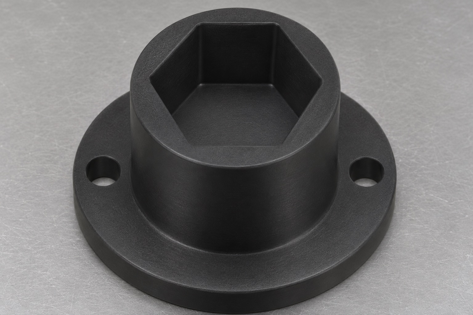
Identify the cap interface before designing the socket
A medical laboratory analyzer may use a custom polymer insert to engage the outside of an identified container cap. This article considers a black POM-C socket with one upward-facing hexagonal blind recess, a wider circular mounting flange and two plain flange holes. It is intended only for an approved external hexagonal cap geometry. It contains no cap, tube, ejector, thread or liquid passage. The component name does not make it compatible with ribbed, round or otherwise different caps. The equipment team must define the actual mate and handling arrangement before manufacturing release.

Map the permitted contact surfaces
Identify which cap flats may contact the socket and which regions must remain clear, including markings, seals or fragile features. Define whether contact is expected during rotation only or also during other handling stages. Do not assume that a close-fitting recess provides controlled gripping or axial retention. The cap's outer geometry, material and permissible deformation belong in the design review. If the insert is expected to transmit motion, the full drive and container-support arrangement must be described. A socket photograph cannot establish acceptable cap loading or reliable closure handling for an analyzer.
Specify the hexagon beyond a nominal across-flats value
Define across-flats size, recess depth, orientation and the permitted internal corner geometry. A milling cutter leaves a radius at an internal corner, which may interfere with the actual cap corner even when side clearances seem adequate. Review an approved corner relief if necessary, including the remaining wall thickness. Do not silently enlarge the whole recess or sharpen it by uncontrolled hand scraping. The actual cap profile should govern the clearance review rather than a generic hexagon drawn around one convenient dimension. Resolve model and drawing differences before the toolpath is released.
Define the floor and insertion envelope
A blind recess has a floor, but that floor is not automatically an intended cap stop. State whether the cap contacts it and how insertion depth is established. Review axial clearance and the surrounding mechanism's approach envelope. The illustrated socket contains no vent, drain, side opening or ejection feature. If the design requires any of these, add them explicitly and review the resulting section and access. Do not infer release behavior from a simple static fit. A socket that admits a cap by hand is not necessarily suitable for automated insertion and withdrawal.
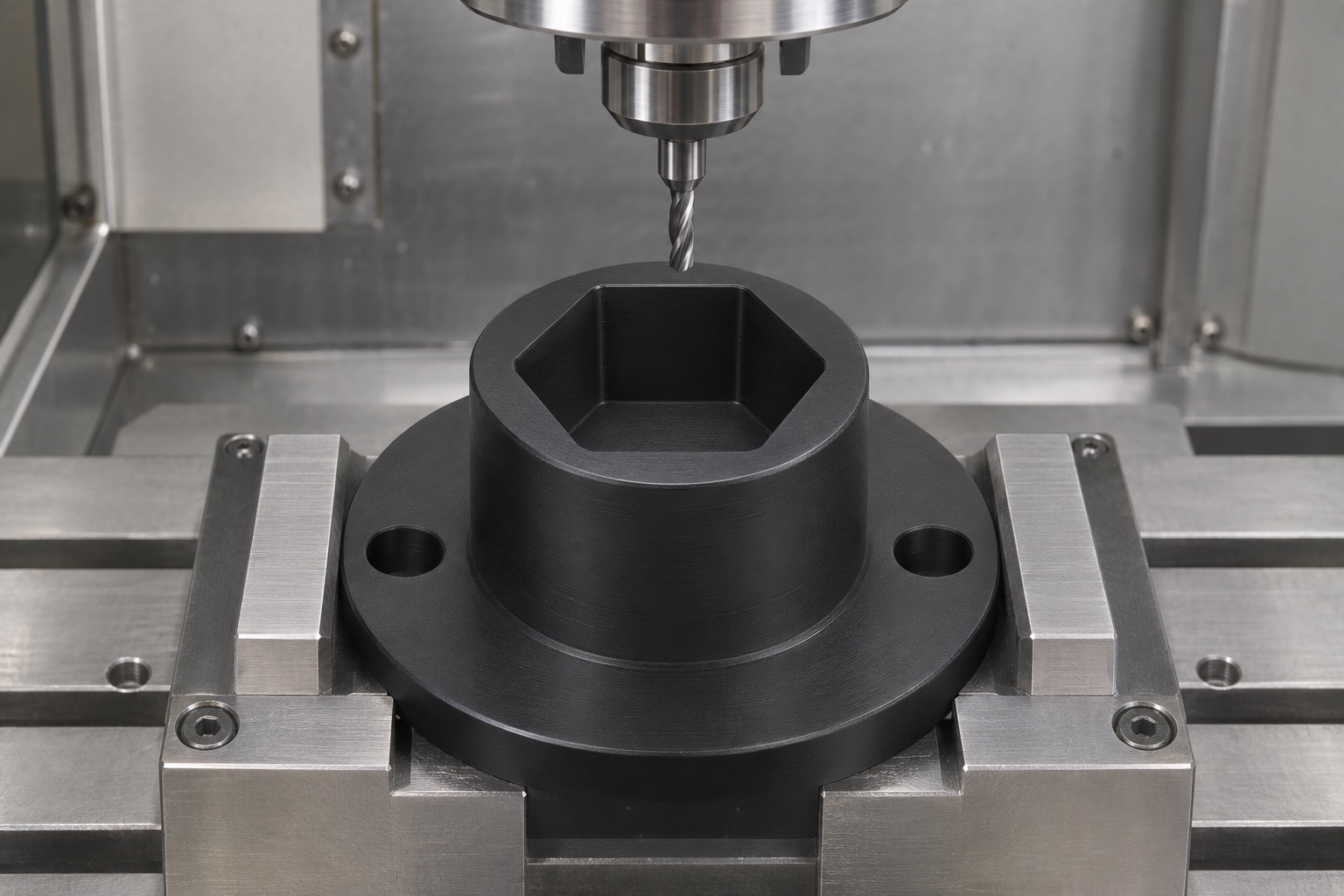
Relate the flange to the working recess
Choose a mounting reference plane and an agreed rotational reference for the recess and two flange holes. Specify how the insert is located on its driving assembly and which features carry the intended contacts. Plain holes alone do not define a precision location or a complete fastening system. Review screw-head seats, tool access and the material remaining around the holes. Threads, metal inserts and counterbores are not included in this concept. If such features are required, document them as approved changes rather than leaving the assembler to improvise a mounting interface.
Specify the polymer and application boundaries
Request the approved POM-C grade, color, stock form and traceability scope. Black appearance is not a material certificate or a medical-grade designation. Ensinger provides general background on POM machining, not qualification of this particular socket. Review the actual cleaning agents, temperature exposure and contact restrictions with the responsible equipment team. Do not infer biological suitability, sterilization compatibility or low particle shedding from machinability. This concept addresses the cap exterior only; contact with samples or reagents would require a revised material, cleaning and application assessment rather than an assumption that the existing insert is suitable.
Plan turning and pocket milling together
The cylindrical body and flange may suggest a turning route followed by milling, but the actual sequence should preserve the approved mounting and recess relationships. Review support, chip removal and access to the blind cavity. Excessive clamping can distort a polymer part, so the delivered inspection condition should not be confused with its temporary workholding shape. Cutting parameters and any conditioning depend on the actual grade, blank and geometry. Protect the finished flange while completing the recess. A supplier should describe a manufacturable proposal without promising a universal plastics tolerance or an untested cap-engagement result.
Inspect the cavity and mounting references
The inspection plan should cover the controlled across-flats dimensions, corner regions, depth, floor and relevant relationship to the flange holes and mounting plane. Select instruments that can access the blind cavity without distorting the walls. Define support and relevant environmental or conditioning requirements. A round plug or one caliper reading does not verify a complete hexagonal interface. An actual identified cap may support a limited fit observation, but it does not replace dimensional evidence. Record the drawing revision, sampled characteristics and acceptance condition so the inspection result is not reduced to a vague statement of fit.
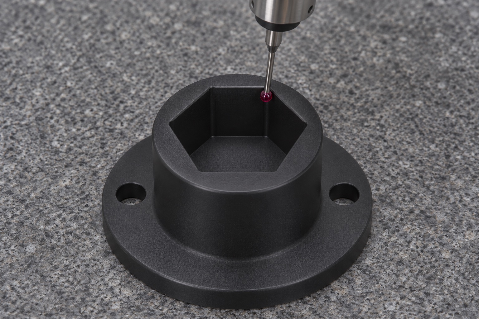
Finish entries without erasing functional flats
An approved lead-in may help insertion, but an arbitrary chamfer can remove a needed contact band. Define edge treatment at the cavity entrance, flange and mounting holes. Remove attached machining material while preserving the approved profile. Do not scrape a socket until a cap enters and then claim the original geometry remains unchanged. Rework needs authorization and inspection. Cleaning should address the contracted component requirements rather than only visual appearance. A smooth black surface is not a measured particle result, validated decontamination or evidence that the insert can safely contact clinical material.
Separate development handling from decapper qualification
An agreed development observation can examine insertion, seating, clearance and withdrawal using identified empty or approved nonclinical components. Record the cap revision, mounting arrangement and procedure. Successful hand engagement does not establish transmitted torque, cap damage limits, axial retention, release reliability, contamination control or analyzer throughput. The complete mechanism requires a relevant evaluation. If binding occurs, review corner contacts and the mounting condition before removing material. Keep modified development inserts identifiable and separate from released production until the approved geometry, program and inspection requirements have been updated.
Protect the recess during packaging
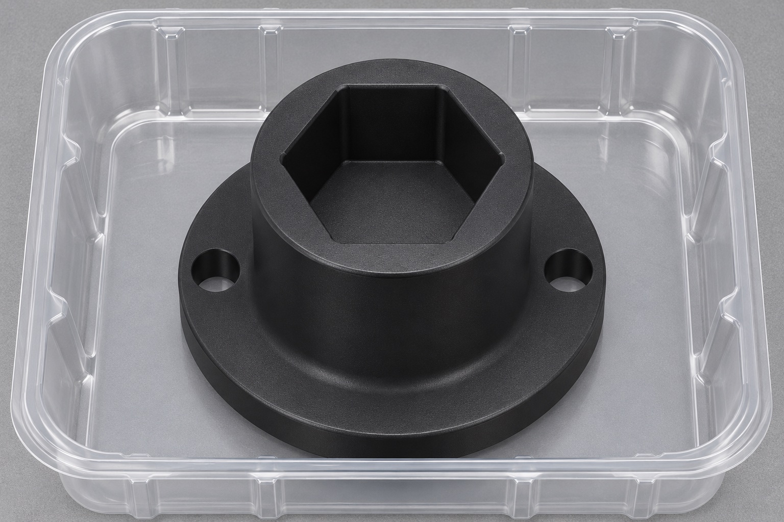
Individual separation should prevent neighboring parts or packaging inserts from forcing the cavity walls outward or marking its contact flats. Keep machining debris and packaging fibers out of the blind recess. Preserve part number, material identity, revision and inspection status on associated documentation. Specify restrictions on protective materials before the supplier chooses a tray or sleeve. Ordinary protective packaging is not sterile delivery. If final cleaning or assembly happens elsewhere, define the handover condition. Do not send a used clinical cap or tube to an ordinary machining area as an informal dimensional reference.
Prepare a cap-specific quotation package
Include the controlled model and drawing, identified external cap profile, permitted contact map, insertion-depth definition, mounting references and any separate gripping or ejection concept. State the polymer grade, quantity, finish, inspection condition and packaging scope. Identify which requirements belong to the machined insert and which require system-level handling evaluation. Resolve missing interfaces before release rather than calling the component a universal decapper socket. This supports a useful CNC manufacturing discussion without confusing dimensional acceptance with clinical suitability, controlled cap loading or qualification of the analyzer's complete automated workflow.
Manufacturer background reference: www.ensingerplastics.com.
FAQ
Will the socket fit any laboratory tube cap?
No. This concept addresses an identified external hexagonal cap only. Round, ribbed or differently shaped caps need their own approved interface. A general cap category or nominal diameter does not establish compatibility, permissible contact or reliable engagement.
Does a tight fit prove gripping or torque capacity?
No. Static fit, axial retention and transmitted torque are different questions. The actual cap, insert, drive, support and procedure need an appropriate evaluation. Dimensional inspection does not independently establish cap damage limits or qualified decapping performance.
Why are internal corner radii important?
A cap corner may interfere with the milled radius even when across-flats clearance appears adequate. Compare actual profiles and permitted contacts, then approve a radius or relief. Do not silently enlarge or hand-scrape the entire recess to hide a local conflict.
Are an ejector, drain or vent included?
No. The concept has a closed blind recess and no release or fluid-management feature. Such additions require an explicit design change and review of remaining material, support and inspection. Do not infer automated release behavior from an empty cavity photograph.
May the socket contact the sample liquid?
Not within this scope. The proposed role is contact with approved exterior regions of a cap. Sample or reagent contact would change the application and require a revised material, cleaning and qualification assessment before any suitability claim could be made.
What is required for a useful inspection report?
Identify the controlled drawing, actual cavity and mounting characteristics, inspection condition, methods and results. An identified nonclinical cap may support a limited fit observation, but that should remain distinct from dimensional acceptance and any complete analyzer handling validation.

tanghangyun@oemach.com