
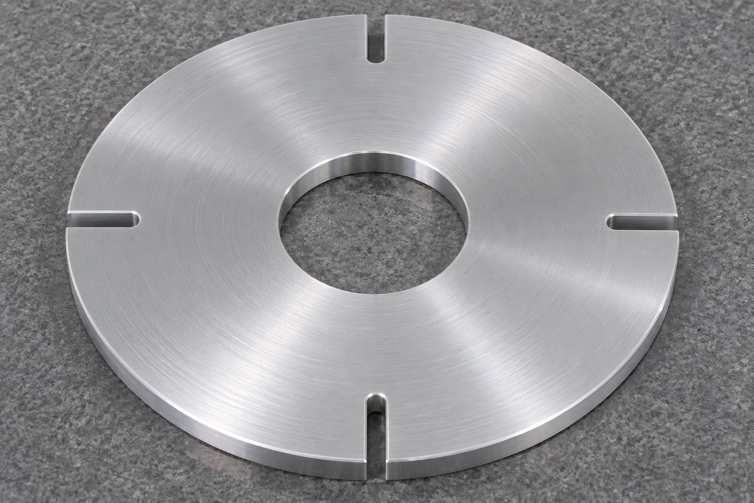
Define the disc and the sensing arrangement
A medical analyzer may use a metal disc as one mechanical element of a position-sensing arrangement. The concept here is a flat 6061 aluminum disc with a smooth central through bore and four short radial slots opening at the rim. The remaining inner annulus is continuous. It has no printed optical track, electronics or supplied sensor. OMRON explains the general optical encoder principle, but this simple component is not a complete encoder. The equipment designer must define the optical path, mounting arrangement and required system behavior before asking a machine shop to produce the part.

Separate an index feature from a resolution claim
Four openings describe a physical layout, not a guaranteed number of usable position states or a certified angular resolution. Sensor geometry, signal processing and the intended reference strategy all matter. State whether the arrangement detects a home position, repeated events or another condition. Do not imply a unique home indication when the approved geometry and sensing arrangement do not provide one. If the design needs unequal openings, an additional track or another reference feature, show it explicitly. A supplier should not modify the pattern based on a guess about the analyzer's control algorithm.
Establish a useful angular reference
A plain circular bore does not identify an angular zero by itself. The released definition should relate slot centers or working edges to a usable reference, or explicitly define the pattern only by its internal relationships where that is sufficient. Identify the orientation method used during assembly and inspection. A keyway, flat, pin hole or marked reference is not included in this concept and must not be assumed. If orientation is established by a fixture or another component, document that arrangement rather than treating an unmarked circular surface as an inherently indexed feature.
Dimension the working slot edges
Specify the slot width, radial extent, end shape and any required relationship among the four openings. State which edges interact with the sensing region and which surfaces provide clearance only. Include the permitted cutter radius at each closed slot end. A nominal opening width does not define all edge locations or angular relationships. Review the remaining material between each slot and the bore. Do not silently extend a slot to suit the available cutter, since that changes both geometry and the mechanical section. Resolve model and drawing discrepancies before programming.
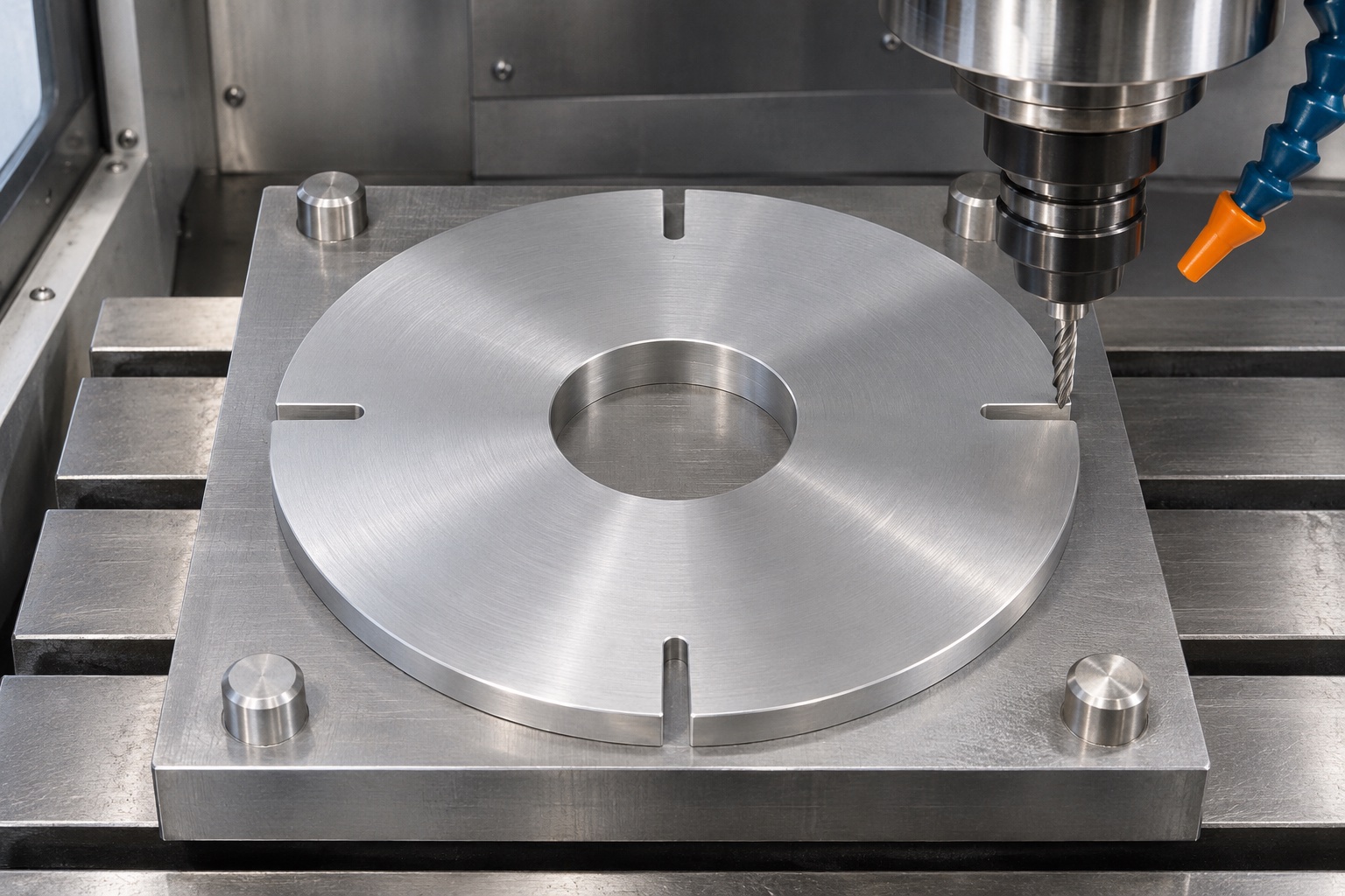
Relate the bore, disc faces and outer envelope
The central bore, mounting contact face and disc outline need an agreed reference system. Define only the geometric controls required by the actual assembly, including any relevant face orientation or runout requirement. State how the disc is supported when those characteristics are inspected. A bore that accepts a shaft does not independently establish the relationship of every slot to that shaft. Conversely, a neat slot pattern does not verify the bore or mounting contact. Discuss the useful assembly references with the inspector before choosing a measurement method or applying unnecessary tight controls to cosmetic surfaces.
Specify material and final optical surfaces
The order should identify the actual 6061 grade, temper, stock form and traceability requirements. Specify any ordered surface treatment and its extent rather than assuming the disc must be bright, black or reflective. Optical behavior belongs to the real emitter, detector, surface condition and geometry; it is not established by the alloy name. If a treatment is included, review the final dimensions and working edges after that process. Do not infer corrosion resistance to a cleaning agent, medical suitability or sterile delivery from a photograph of a clean aluminum disc.
Support the plate through material removal
The machining proposal should relate facing, bore generation and slot cutting through the required setups. Consider support beneath the disc and access near the rim without treating a clamped shape as the delivered condition. The remaining annulus must stay intact as defined. Actual tool selection, stock allowance and cutting parameters depend on the dimensions and machine; no universal recipe is proposed here. Protect completed faces during later operations. Inspect the agreed final state after release from workholding, or in another explicitly specified condition, rather than reporting only a convenient in-fixture measurement.
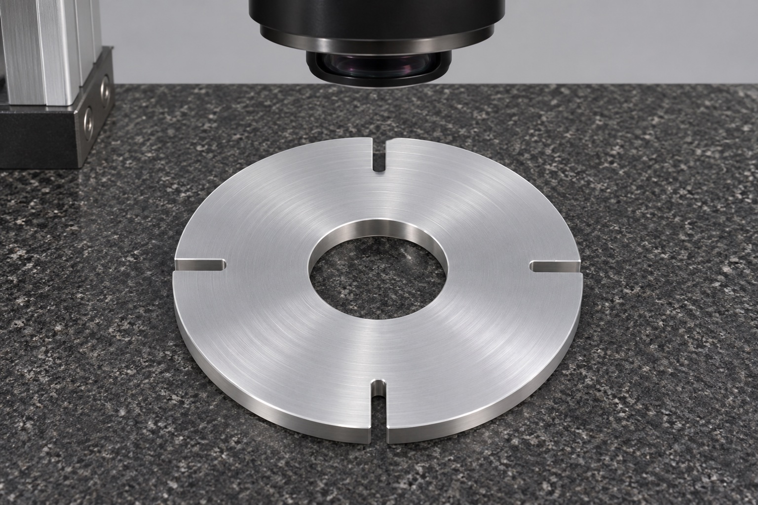
Choose inspection suited to the openings
An optical measurement system may be useful for visible slot edges, while bore and face relationships can require additional methods. Select instruments and sampling according to the controlled characteristics and required uncertainty. Record the orientation reference and support arrangement. A two-dimensional silhouette alone may not reveal a burr, taper or edge condition through the full thickness. A caliper width check does not document the angular pattern. Combine appropriate checks instead of claiming that a single photograph or instrument verifies the complete disc. Real reports must contain actual observations and measured results.
Deburr without moving the sensing edges
Define edge treatment at the slots, outer rim and bore. An uncontrolled chamfer or rounded edge can change the effective opening geometry seen by the sensing arrangement. Remove attached burrs according to the approved requirements without polishing away a working edge merely to improve appearance. Review the closed slot ends and both faces, not only the most accessible side. If rework changes a controlled feature, obtain authorization and inspect it again. Cleaning should follow the contracted component process. Visual cleanliness is not a particle-count result or evidence of validated disinfection.
Keep a sensing trial separate from part acceptance
An agreed development trial can observe clearance, installation and sensor response with identified components and a recorded procedure. It does not by itself demonstrate encoder accuracy, resolution, timing stability, speed capability or analyzer safety. The complete mechanical and electronic arrangement needs its own evaluation. A satisfactory signal at one hand-turned position is not a validated operating envelope. If a signal is unexpected, review the sensor and reference geometry before enlarging the slots. Preserve development samples and record any approved change instead of using a manually altered disc as an undocumented production master.
Protect the rim and maintain identification
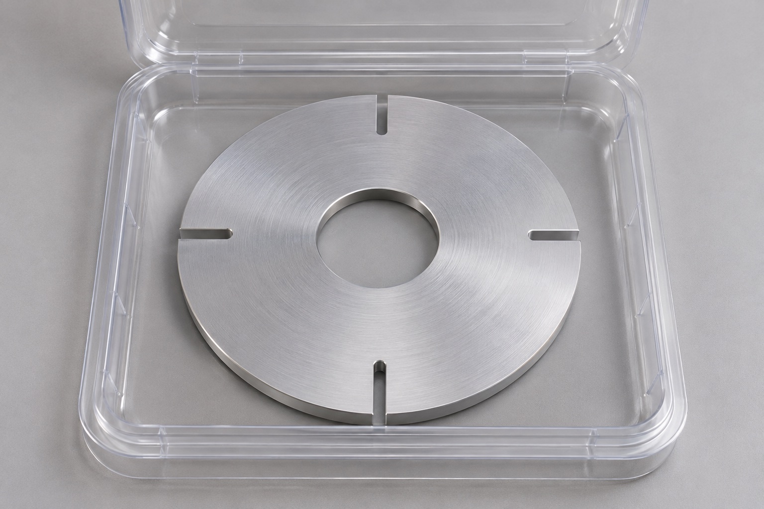
Individual packaging should keep slot edges and disc faces from striking adjacent parts. Supports should not bend the plate or force material into the openings. Identify the part number, revision, material condition and inspection status on associated documentation rather than adding an unapproved marking to the sensing region. Agree cleaning and packaging restrictions before selecting protective materials. Ordinary trays and sleeves are not sterile packaging. If the purchaser performs final cleaning or assembly, define the handover condition. A protective package does not establish that the disc is balanced or qualified for rotation at any particular speed.
Prepare a sensing-interface manufacturing request
Provide the model and drawing, reference strategy, slot-edge definition, shaft and mounting interfaces, material condition, surface treatment, inspection plan and packaging scope. Explain the mechanical role without asking the supplier to infer the control logic. State which requirements apply to the machined disc and which belong to a separate system trial. Resolve missing orientation information before release. This produces a specific CNC quotation discussion while keeping component geometry, optional sensing observations and medical analyzer performance as separate decisions. No electronics, measured accuracy or complete qualified encoder are implied by the illustrative concept.
Manufacturer background reference: www.ia.omron.com.
FAQ
Does the four-slot disc have a guaranteed angular resolution?
No. The slot count is a geometric description. Usable sensing states and resolution depend on the actual sensor, mounting and signal processing. A machined disc and its inspection report do not independently establish encoder performance or a qualified analyzer operating range.
Where is angular zero on a plain circular bore?
The bore alone does not define it. The drawing and assembly must provide a usable orientation strategy, or define the pattern only by its internal relationships where appropriate. A keyway, flat, pin hole or reference mark would require an explicit approved feature.
Can the slots be extended to simplify machining?
Not without an authorized design change. Slot extent affects the sensing opening and remaining mechanical section. Resolve cutter access and end radii during review, then manufacture and inspect the approved geometry rather than silently adapting it to an available tool.
Does an optical silhouette inspection cover every requirement?
Not necessarily. It may document visible edges but not all through-thickness conditions, burrs, bore relationships or mounting-face characteristics. The inspection plan should combine methods that address the actual released requirements and their relevant uncertainty.
Is a black surface finish mandatory?
No finish is universal. Specify the required surface condition and review it with the real sensing arrangement. If a treatment is supplied, include its effect on final geometry and inspection. Appearance alone does not establish optical behavior or medical suitability.
Does this article include a balanced high-speed rotor?
No. The concept is an illustrative index disc, not a rated rotor or complete encoder. Any speed, balance, retention or safety requirement needs the actual geometry, assembly and relevant evaluation. Protective packaging and dimensional acceptance do not establish those results.

tanghangyun@oemach.com