
Define a one-piece mechanical adjustment interface
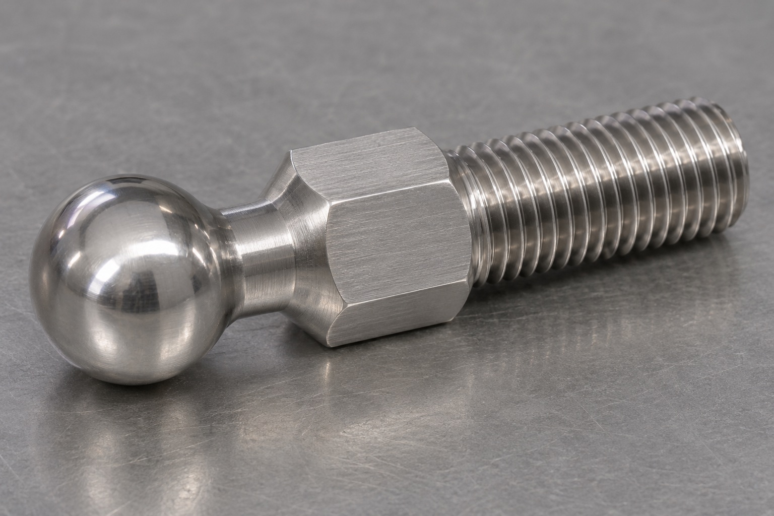
A medical equipment service or alignment mechanism may use a custom stud to introduce an adjustable contact. The concept discussed here is a one-piece 316L component with an integral spherical end, a short neck, a hexagonal wrench section and an external male thread at the opposite end. The ball is not a separate rotating element, and the part is not a complete ball joint. Its intended use is an internal mechanical interface, not an implant or fluid-path fitting. The equipment designer must define the mating contact, adjustment range, retention arrangement and operating requirements before manufacturing is released.

Distinguish a spherical tip from a qualified joint
A rounded end can change the way contact occurs, but its presence alone does not establish an articulation range, allowable force or resistance to wear. Identify whether the mate is flat, conical, spherical or another controlled shape. State the intended contact region and whether sliding or rotation is expected during adjustment. A one-piece tip rotates with the stud when the threaded portion turns unless another mechanism changes that motion. Do not describe it as a freely rotating ball or promise that it prevents marking. Those statements require a different design definition and relevant evidence.
Specify the spherical geometry and its reference
Define the spherical radius or diameter, permitted extent of the spherical surface and relationship to the threaded axis. Include the neck transition and any relief required by the approved mating envelope. A polished-looking tip does not define its form or position. If the contact depends on a limited angular region, show that region and the clearance around it. Avoid an ambiguous overall length measured to a hypothetical point when inspection needs a usable reference. Agree the controlling characteristics and a measurement method that can actually evaluate the finished geometry without assuming inaccessible mathematical centers are directly observable.
Identify the thread beyond its nominal diameter
The thread definition should state system, pitch, hand, fit and the useful threaded length required by the assembly. Review the entry, runout and any shoulder before treating the full visible thread length as usable engagement. The mating component and any locking arrangement need their own approved definitions. Do not select a thread by trying an available nut and assuming the interface is complete. A thread gauge can address specified thread requirements, but it does not independently prove the joint's load capacity, adjustment stability or safe retention in a medical equipment mechanism.
Keep wrench access and contact position compatible
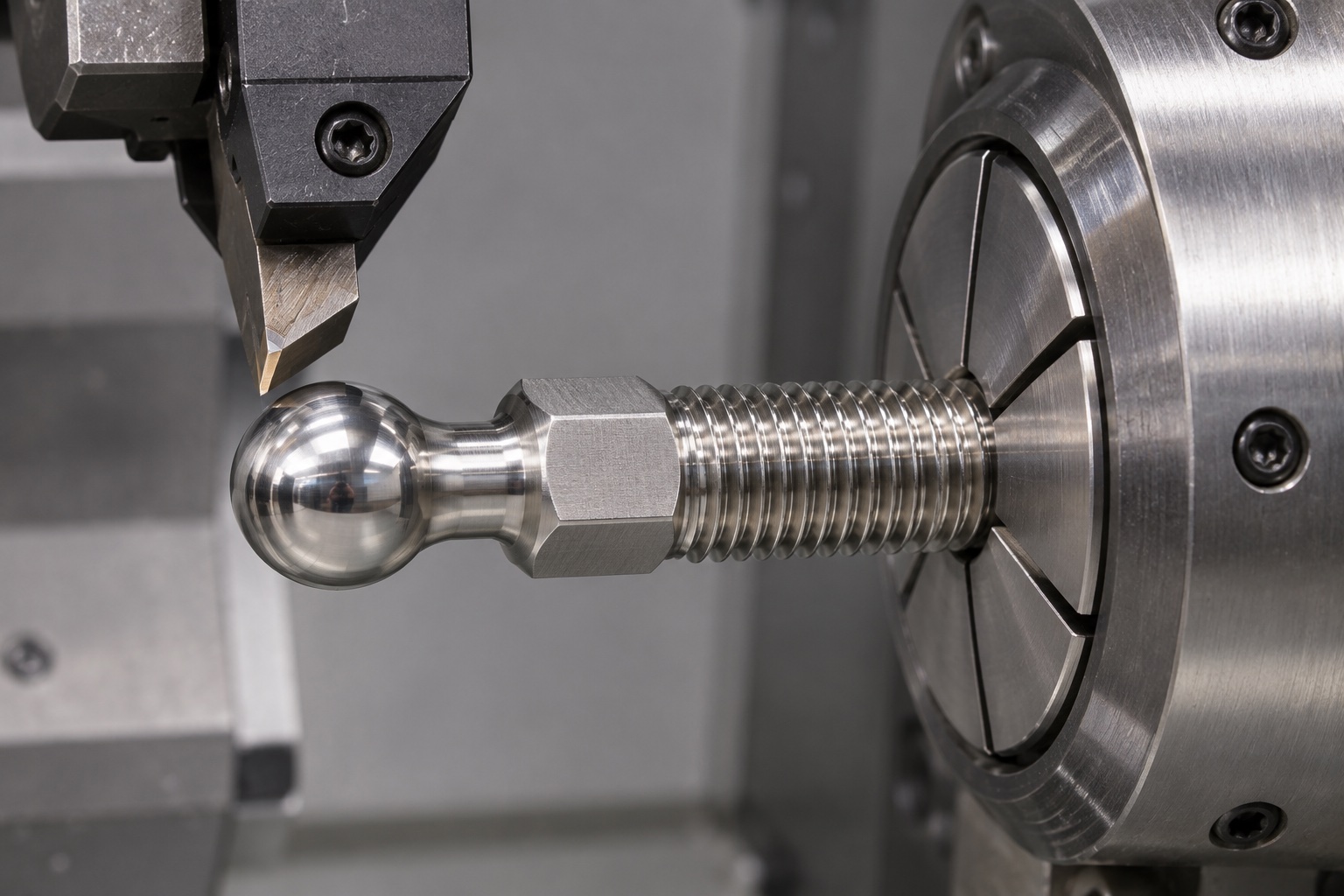
Define the hexagonal section across flats, its length and the transitions at both ends. Check the actual wrench envelope against nearby equipment parts through the required adjustment range. A tool must be able to turn the stud without striking the mate or damaging the spherical contact. State whether an additional locknut is part of the assembly; none is supplied by the illustrative component. If the mechanism requires access after a cover is installed, review that condition specifically. A compact drawing that omits the surrounding assembly can hide a service-access conflict even when every machined dimension is correct.
Specify the stainless steel and final surface process
The order should identify the exact 316L specification, stock form and traceability requirements. Similar appearance is not proof of grade or condition. State any ordered passivation, polishing or other finishing and review its effect on threads and contact surfaces. Do not equate a stainless alloy with universal chemical resistance, validated cleanability or suitability for every medical environment. The final acceptance state should be explicit, including which characteristics are inspected after any contracted treatment. General commercial examples of ball-point screws provide interface context, not evidence that this custom component has a particular certified load or wear rating.
Plan turning and milling around shared references
A proposed route may combine turning for the thread and spherical end with milling of the wrench flats. The sequence should preserve the approved relationship among these features through workholding changes. Assess tool access near the neck and thread runout without inventing a universal machining recipe. Actual cutting conditions, stock allowance and support depend on the part dimensions and equipment. Protect the completed spherical surface during later operations. Where a temporary center, grip allowance or fixture contact is used, define how it is removed or kept outside the approved contact region in the delivered component.
Select inspection methods for the actual characteristics
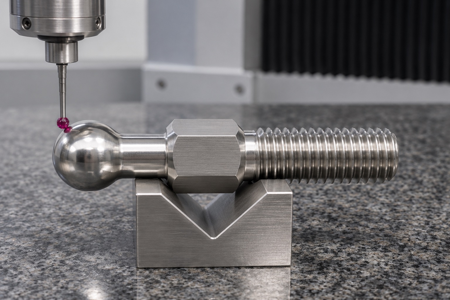
The inspection plan should address the spherical form or profile, its position relative to the approved axis, the neck geometry, wrench section and thread. Suitable instruments depend on access, required uncertainty and drawing controls. A diameter reading at one location does not establish an entire sphere, and a ring gauge does not evaluate every relationship between the thread and tip. Record support and sampling so that the results are understandable. Avoid reporting numerical conformity from a generated photograph. A real acceptance report must identify measured characteristics, actual results and the controlled document against which they were assessed.
Finish transitions without changing the working contact
Thread entries, wrench edges and neck transitions should be free of attached burrs according to the approved requirements. The spherical contact needs a defined finish rather than uncontrolled buffing until it looks bright. Excessive polishing can change the contact envelope or obscure a defect without resolving it. If a local rework is proposed, authorize it and inspect the affected characteristics. Keep machining debris and abrasive residues out of the finished thread. Cleaning remains a specified component process; visual shine is not evidence of measured cleanliness, biological suitability, validated disinfection or sterile supply.
Evaluate adjustment separately from dimensional acceptance
An agreed assembly observation can record wrench access, adjustment travel and contact with an identified mating component. It should identify thread engagement and any separate retention parts without inventing an assembly torque. Successful hand adjustment does not establish axial load capacity, contact stress, locking stability, fatigue life or wear resistance. Those require a relevant evaluation of the actual mechanism. If contact is unexpected, review the mate and reference geometry before grinding the tip. A development sample altered during a trial should remain traceable and separate from production until approved changes are incorporated into the released definition.
Protect the tip and thread in the package
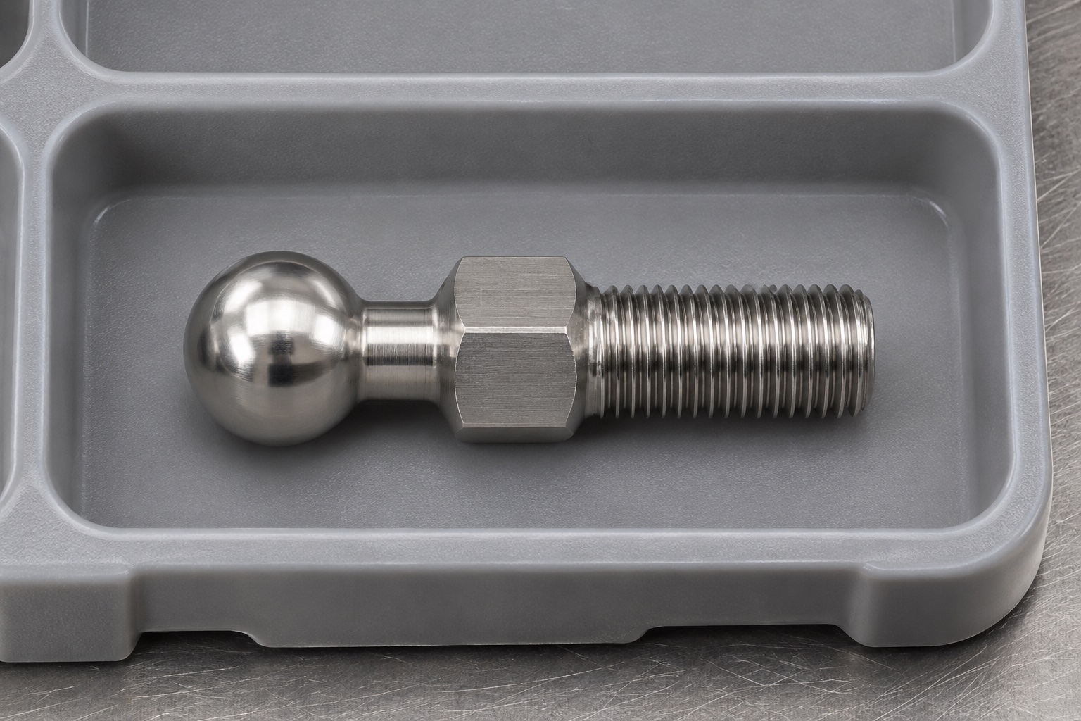
Individual separation should prevent the spherical contact from striking another part and keep the external thread from damaging neighboring surfaces. The packaging proposal should also preserve component identity, revision and inspection status. A cap or sleeve, if used, must not leave prohibited residue or impose an unwanted contact on the tip. Specify any material restrictions and cleaning handover before selecting the packaging. Ordinary protective packaging does not establish sterility. A photograph of several shiny studs in a tray should not be presented as proof of a production lot or a verified medical equipment delivery.
Prepare a contact-specific manufacturing inquiry
Provide the controlled model and drawing, mating contact definition, thread specification, wrench-access envelope, material condition, final finish and inspection requirements. Identify the useful adjustment range and any separate locking concept without assigning unverified performance to the stud itself. Resolve discrepancies between the spherical profile in the model and the dimensions on the drawing before machining. Request evidence appropriate to the characteristics that matter. A clear manufacturing package enables a meaningful quotation while keeping component geometry, optional assembly observations and device-level performance or safety validation as distinct activities with explicit responsibilities.
Manufacturer background reference: www.elesa-ganter.com.
FAQ
Is the spherical end a separate rotating ball?
No. The proposed stud is one piece, and the integral spherical tip turns with it. A captured rotating ball or assembled ball joint is a different construction. Do not infer articulation, friction reduction or wear performance from a spherical-looking end alone.
What thread information is needed before machining?
Specify the thread system, nominal size, pitch, hand, fit, useful length, entry and runout, together with the mating interface. A nominal diameter or a nut that happens to screw on is not a complete manufacturing and inspection definition.
Can the load capacity be inferred from 316L material?
No. Capacity depends on the complete geometry, contact pair, thread engagement, loading and operating conditions. Material identification and dimensional inspection do not establish a system load rating. Evaluate the real mechanism with an appropriate engineering and verification plan.
Does a thread gauge verify the spherical contact?
No. Thread gauging addresses the specified threaded feature within its scope. The tip profile, neck and their relationship to the approved axis require their own inspection characteristics and methods. A single passing check cannot stand in for the complete drawing.
May the tip be polished until the mechanism fits?
Not without an authorized rework decision. Polishing changes geometry and potentially the contact location. Review the mate and references first, incorporate approved changes into controlled documents and inspect affected features instead of using an undocumented adjusted sample as a production master.
Does this concept include a locknut or sterile supply?
Neither is included. A separate locking arrangement and any special cleaning or packaging scope require explicit definition and review. An individually protected stud is an ordinary mechanical component, not evidence of a complete qualified or sterile medical adjustment system.

tanghangyun@oemach.com