
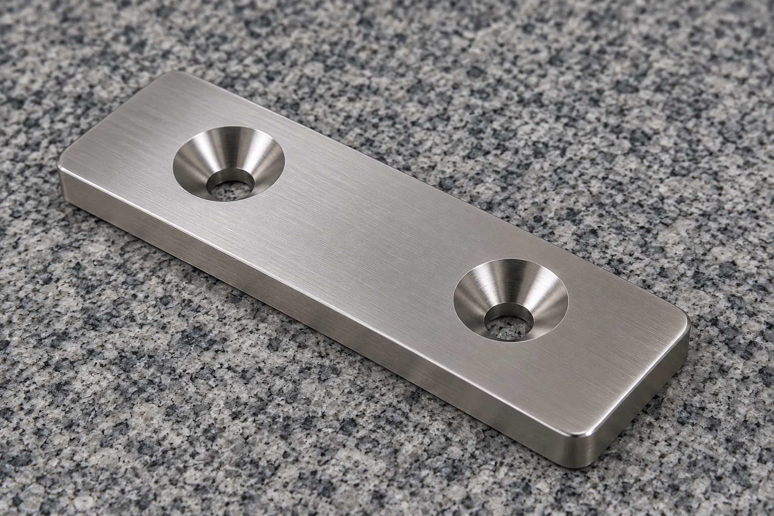
Define the plate and its mounting role
A compact attachment inside a medical laboratory instrument may use a flat mounting plate with recessed screw heads to preserve a defined clearance envelope. The illustrated concept is a uniform-thickness 316L stainless steel rectangle with modestly rounded outer corners and two aligned through holes. Each opening has a conical countersink on the top face and a smaller plain bore below it. No thread, screw, mating frame or additional locating feature is shown. The drawing must define the actual mounting function; this is not an independently qualified structural connection, precision locator or medical safety restraint.

Identify the actual screw and mating stack
Obtain the controlled plate drawing and model, exact fastener head specification, mating component, thread arrangement and instrument revision. Establish how the screws enter, where they engage and which surfaces provide support. A nominal screw diameter does not define its head angle, head envelope or required seat. Do not assume that visually similar countersunk fasteners are interchangeable. Review installation and removal access with the full surrounding assembly. The isolated component image supplies neither a tightening instruction nor a tested connection. Missing fastener and support requirements should be resolved before the supplier selects cutters or acceptance methods.
Distinguish a countersink from a counterbore
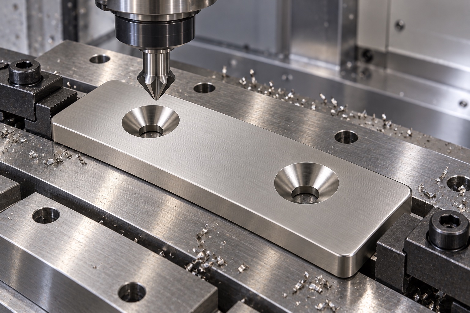
A conical countersink and a cylindrical flat-bottom recess are different seat geometries. The controlled drawing must state the intended form, angle, size or depth definition and any relevant relationship to the plain bore. A circular opening seen from above does not establish these features. Do not substitute a counterbore because its tool is available or describe any recessed hole as the same interface. Where model and drawing express the seat differently, resolve the conflict before machining. The intended screw-head contact should follow approved geometry rather than the supplier's interpretation of a familiar photograph or silhouette.
Relate the cone to the finished top face
Identify the face from which the seat requirement is defined and how final surface processing affects that reference. Define the relevant cone geometry and its relationship to the bore, not just an apparent opening diameter. The screw-head position depends on the real screw and seat together; a matching top diameter alone does not prove the required assembled envelope. Avoid making a cone deeper until one unidentified screw appears flush. Such an adjustment can change the remaining section and actual contact. Record authorized decisions in controlled dimensions and inspection rather than accepting an attractive seating photograph as measurement.
Control bore pattern and remaining sections
Specify each plain bore, spacing, location, through depth and required relationships to plate edges and support contacts. Review the material remaining below and around the conical seats using the actual plate geometry. No universal minimum thickness, spacing or load rating is established by this example. Two acceptable hole diameters do not verify the pattern, and two screws entering a frame do not independently establish alignment. Do not enlarge a bore, shift a center or deepen a recess to fit an unidentified assembly. Those changes require design approval and relevant revised inspection before production can remain repeatable.
Define the broad support faces
Identify finished thickness, useful top and bottom regions, permitted edge treatment and required face relationships. Clarify whether the plate rests on a continuous support or designated contact lands in the real instrument. A plate that can be pulled flat by screws is not automatically acceptable in the specified delivered condition. Do not use assembly force to conceal distortion, add an unapproved shim or remove local stock to eliminate rocking. Component geometry and the complete fastened connection are different engineering scopes. Required preload, stability or loading behavior needs its own approved definition and supporting application evidence.
Specify 316L and the real final process
State the approved 316L stock form, condition, lot evidence and purchased end treatment. A silver finish does not establish hardness, corrosion performance, passivation or a validated cleaning state. Preserve identity through blank preparation, bore and seat operations, inspection and dispatch. Review processes that can affect the functional cone, bore or broad support faces, and identify appropriate final checks. Material documentation identifies stock within its scope; it does not qualify the assembled fastening, biological suitability or sterile delivery. Define any relevant surface and environmental requirements separately for the actual finished component and instrument.
Plan bores and seats with common references
Relate support faces, plain holes and conical seats through the actual machining sequence. Review stability, cutter access and the remaining sections around each recess. Sandvik Coromant's drilling information identifies hole geometry, component material and holding as planning considerations; it is general background, not an approved route or guaranteed result for this plate. Protect useful contacts and remove chips before repositioning. Intermediate observations can guide development, but final acceptance concerns the agreed finished condition. No universal tool setting or achieved cone tolerance is prescribed. A convenient setup should not silently replace the controlled drawing.
Inspect the conical seats as well as the bores
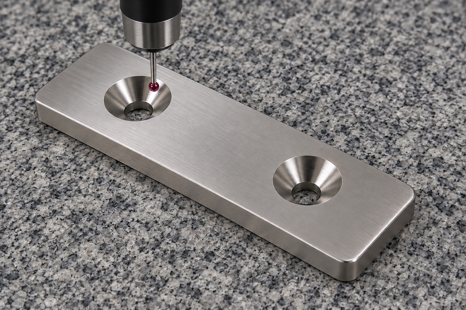
Map cone requirements, plain bore sizes, pattern, finished thickness, faces and relevant relationships to accessible inspection methods. Agree references, support and final state before acceptance. A plug entering the small bore does not inspect the conical seat, and a caliper opening measurement does not establish every angle or contact relationship. If access is limited, choose an appropriate method rather than accepting the plate only because screws can enter. A real report should identify revision, lot, numbered characteristics, methods and observations. The measuring-machine illustration supplies no achieved tolerance, flushness result or verified contact pressure.
Deburr without rounding away the seat
Inspect through exits, cone-to-bore transitions, outer edges and face boundaries for attached material or unintended sharp features. Apply approved edge treatment while preserving the useful screw-seat contact and remaining plain bore length. Polishing until a screw settles lower can hide a geometric discrepancy and requires authorization. Cleaning should follow the purchased scope. A bright smooth surface does not prove measured particles, validated disinfection or sterile delivery. Where identification is required, agree a location outside the defined support and conical contacts, rather than marking or blending a functional surface merely for visual convenience.
Bound assembly observations and protect the geometry
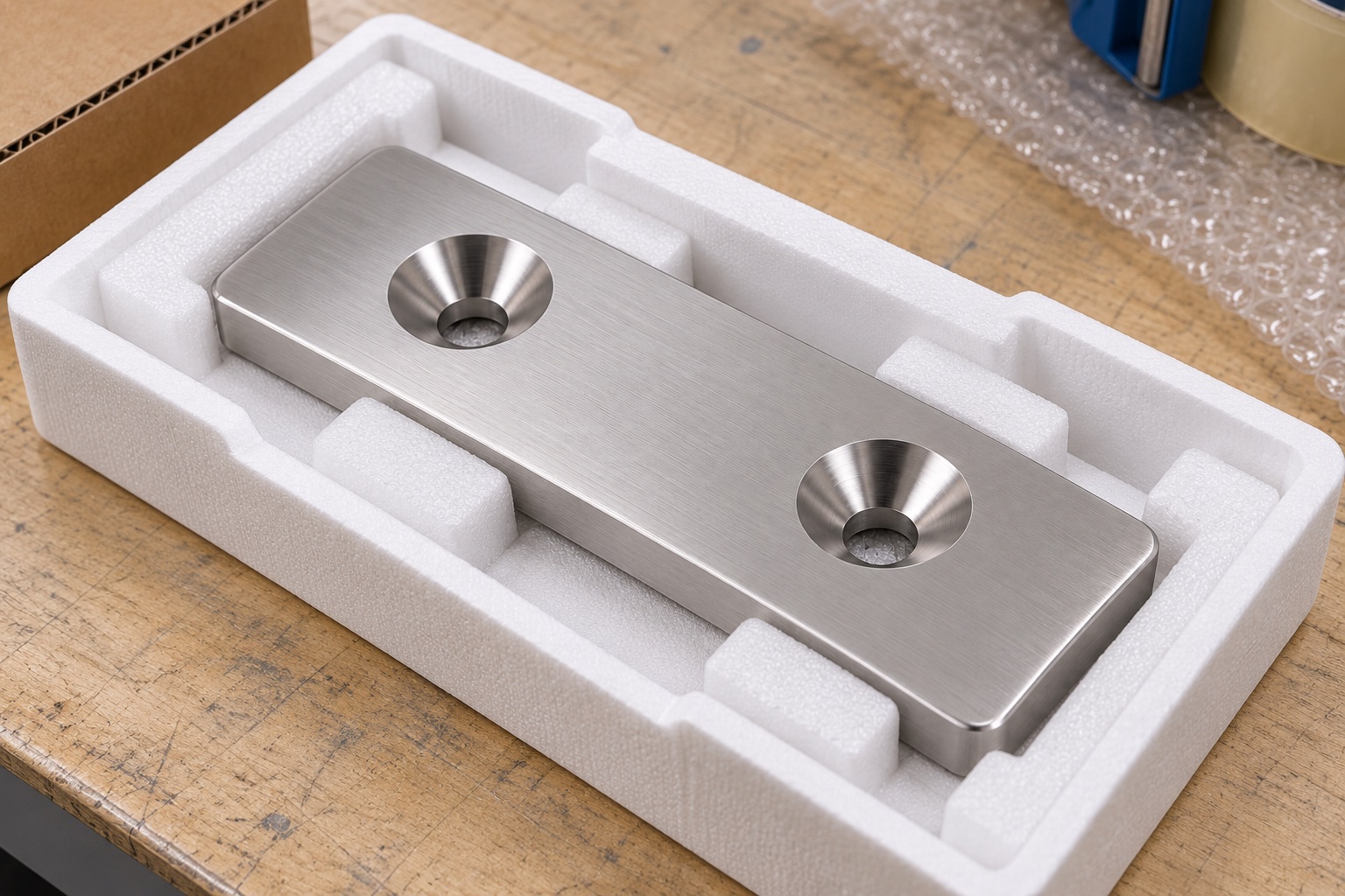
A separately agreed trial may observe screw access, seating and surrounding clearance using identified plate, fastener and mating-part revisions. Record orientation and the approved assembly procedure. Apparent flushness or easy tightening does not establish preload, load capacity, fatigue, vibration behavior or safe restraint; those require separate evaluation of the actual complete connection. Keep trial pieces distinct from production. During dispatch, protect both conical seats and broad faces from loose hardware and impact without bending the plate. Mechanical protective packaging does not imply sterile supply or complete device qualification.
Prepare a screw-seat-specific inquiry
Provide controlled geometry, exact fastener and head specification, mating stack, useful faces, allowed installed envelope, installation access, material, final processes and inspection deliverables. Separate optional fitting from fastening and device-performance qualification. Review changes to screws, frame, surface treatment or assembly procedure before repeating manufacture. Incorporate approved prototype adjustments into revised documents rather than preserve a manually deepened recess as the next production master. This defines a traceable CNC project without inventing measured seating results or confusing an accepted stainless plate with a universally qualified mounting or medical-equipment safety system.
Manufacturer background reference: www.sandvik.coromant.com.
FAQ
Is a conical countersink the same as a flat-bottom counterbore?
No. They are distinct screw-seat geometries. The actual drawing must identify the required form and dimensions together with the exact fastener. A circular top view or a familiar recessed-hole appearance does not authorize substituting one geometry for the other.
Does the screw's nominal diameter define the seat?
No. Head angle, envelope, contact and the approved seat definition also matter. Review the actual fastener and finished plate together. Neither an isolated image nor a screw entering the small bore establishes the correct head position, contact or tightening procedure.
Can a countersink be deepened until the screw looks flush?
Only through an authorized geometry change and relevant inspection. First review the exact screw, cone requirement, face reference and remaining sections. An attractive seating photograph is not a dimensional record, and a hand-adjusted recess must not silently replace the approved drawing.
Does a bore gauge inspect the conical seat?
Not by itself. The plain bore and conical region have distinct requirements. Use an agreed inspection plan covering the seat, hole pattern, thickness and useful faces in the specified finished condition. A screw or plug passing through one opening is not a complete report.
Does apparent flushness prove fastening performance?
No. It is a limited observation with identified parts. Preload, load, fatigue, vibration and operating restraint require separately defined evaluation of the actual assembled connection. Component dimensional acceptance or a smooth 316L surface supplies none of those results automatically.
What should a repeat order review?
Review fastener identity, seat form, cone definition, bore pattern, support faces, remaining sections, material and final processing. Check access and the mating stack if the instrument changed. Approved adjustments belong in controlled documents, not a sample with manually deepened seats.

tanghangyun@oemach.com