
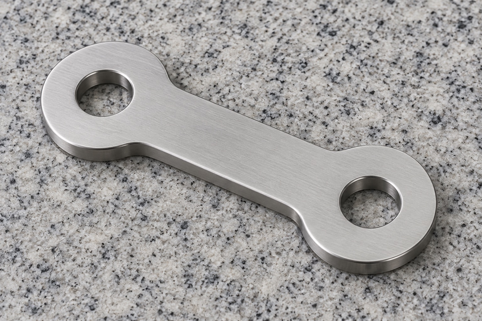
Representative proposed two-hole link
This representative example proposes a one-piece flat 316L stainless tie link for an equipment-side service mechanism in a medical laboratory instrument. The component has two broad rounded ends joined by a narrower waist, uniform thickness and two plain equal-size through holes. No threads, inserts, bearings, pins or retention hardware are included in the illustration. No actual customer delivery, manufactured specimen or measurement record is described. Achieved tolerances, load capacity, fatigue life, wear, retention, sterile status, medical certification and complete-mechanism safety are not claimed as actual measured outcomes. This is a proposed component route, not a rated linkage assembly.

Review both actual mating connections
The proposed order would begin with the controlled drawing and model, both pin or fastener specifications, adjacent members, spacers and actual equipment revision. The designer would identify hole function, permitted movement, side clearance, installation order and retention. An isolated link image would not select a pivot, bearing or washer. The supplier would clarify missing interface information before choosing operations. Component manufacture, optional assembly observation and full-mechanism qualification would remain separate deliverables. Two convenient rods fitting the part would not define a universal accepted interface or demonstrate that the instrument's linkage operates safely under intended service conditions.
Keep the approved 316L evidence traceable
Material records would identify stock form, condition, lot and purchased final processes. The supplier would not substitute another silver alloy or transfer a commercial link's rating to the proposed custom component. Blank allowance would follow the actual holding and finishing plan. Identity would remain associated through profile machining, hole operations and packaging. Stock evidence would identify material within its scope, not prove hardness, wear life, corrosion performance or sterile status. Any property required by the real linkage would need a separately agreed requirement and supporting evidence for the finished component and actual application rather than a generic appearance or material name.
Establish face references and support
Initial operations would create the useful broad face and thickness references needed to relate holes and profile. Holding contacts would protect functional areas and avoid forcing a misleading shape into the plate. Chips would be removed before reorientation. The supplier would review reference transfer rather than reset each feature from a convenient raw edge. Intermediate observations could assist route planning, but final acceptance would address the agreed delivered condition after relevant processes. A link that appeared flat only under strong restraint would not automatically satisfy the drawing or establish the side-clearance condition of the actual retained linkage assembly.
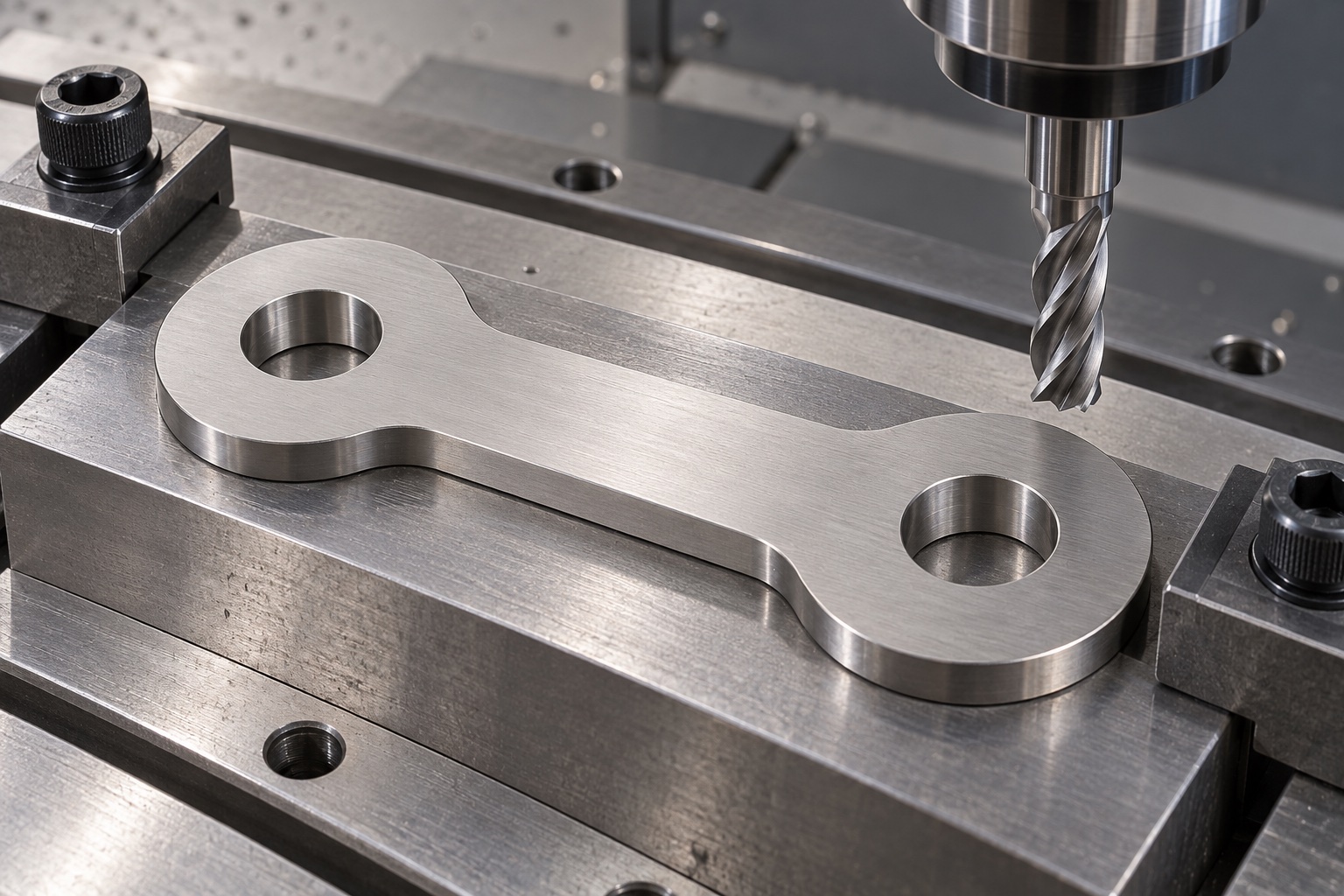
Machine the two controlled plain bores
Each hole would follow released size, through depth, entry requirements and location relative to accepted references. The center-to-center relationship would remain a distinct requirement, not inferred from the two diameters or outside length. Sandvik Coromant's drilling guidance would provide general process background for hole geometry, material and holding, not an approved recipe or guaranteed result for this component. The supplier would not shift a center, open a hole or add a slot to fit an unidentified assembly. Drawing and model conflicts would be resolved before finishing, and authorized changes would enter controlled geometry and inspection documents.
Preserve the rounded ends and waist transitions
The outer profile, remaining material around the bores, connecting waist and transitions would follow approved geometry. Tool access and support would be reviewed before final operations. A visually familiar outline or a convenient cutter radius would not silently replace required dimensions. The supplier would not narrow the waist or polish an end until a particular mechanism moved freely. Such proposals would require design approval and revised inspection where relevant. Component acceptance would remain distinct from establishing load, fatigue margin, wear or complete-system behavior of the link, pins and neighboring members in the actual medical instrument.
Maintain finished thickness and useful contacts
The actual drawing would define thickness, broad faces, end contact areas and relevant relationships to the mating stack. Noncontact edge breaks would remain distinguishable from surfaces that set axial spacing or support the connection. The supplier would not locally thin an end or add unshown washers to complete an ambiguous fit. Purchased final-process effects would remain in the route and appropriate checks. A link assembled over two pins would not by itself demonstrate side clearance, free movement or retention after all hardware was fitted. Those relationships would be defined and evaluated with the complete actual assembly rather than inferred from the isolated plate.
Finish edges and clean without changing the pattern
The supplier would inspect both bore mouths, through exits, outer edges and waist transitions for attached material or unwanted sharp features. Approved edge breaks would preserve useful bore length, profile and contact areas. Hand polishing to improve one pin fit would require authorized review, not disappear as cosmetic finishing. Cleaning and final processing would follow the purchased scope. A smooth stainless surface would not prove measured particles, low friction, validated disinfection or sterile delivery. Lot, revision, material evidence and authorized adjustments would remain linked to the actual finished link before inspection and mechanical protective packaging.
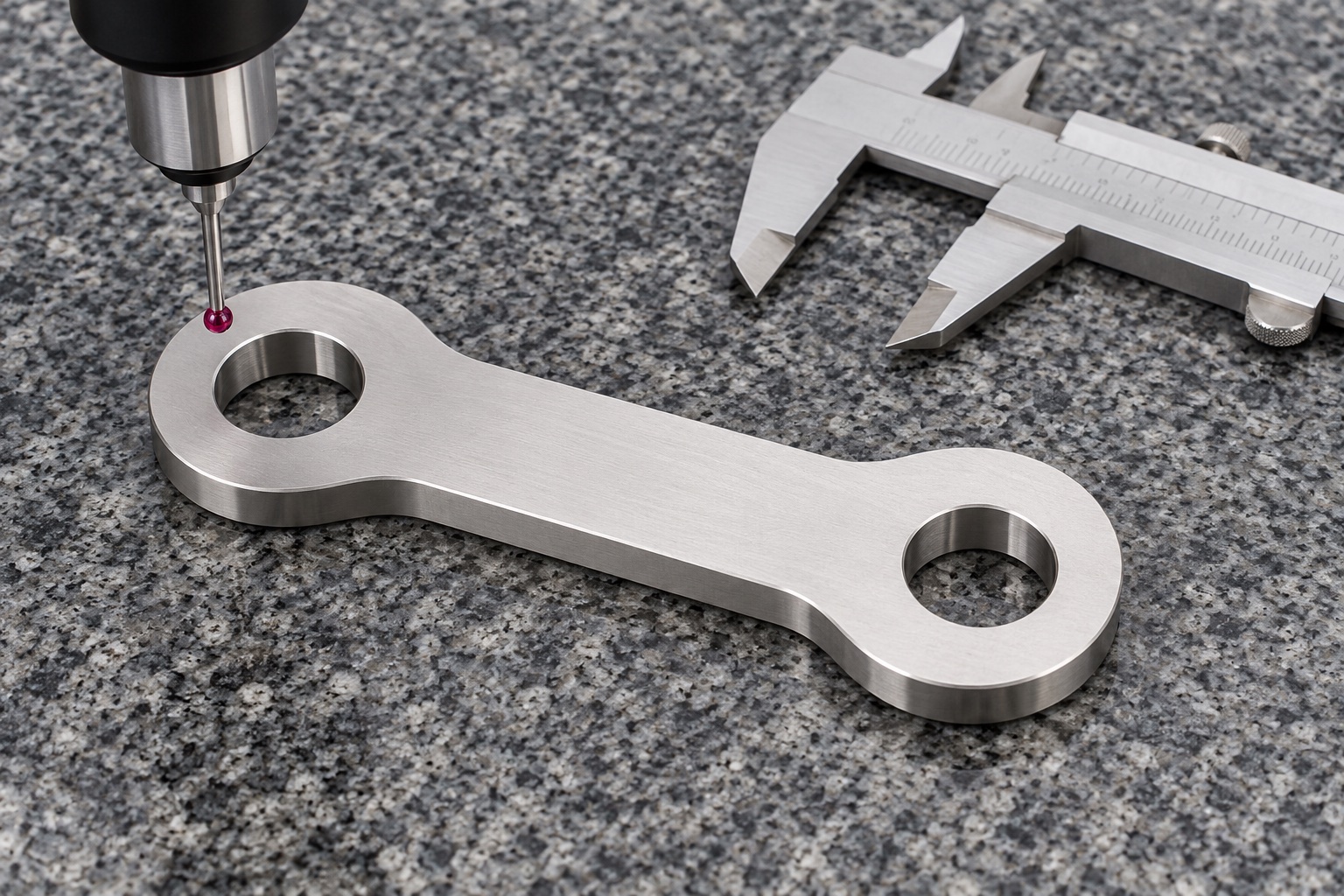
Inspect the final related geometry
The proposed plan would identify methods for both bores, center distance, thickness, useful faces and required profile relationships. Support, references and final state would be agreed. One pin in each opening or an outside-length caliper reading would not verify every feature. Inaccessible regions would be resolved before acceptance. A CMM illustration would show a possible setup, not an achieved tolerance. Actual observations in a real order would refer to the finished component after relevant processing, not a fixture-constrained appearance, an unidentified two-pin sample or a favorable hand movement used as a substitute for controlled dimensional requirements.
Build records without invented linkage results
The proposed report would identify revision, material lot, final condition, numbered characteristics, methods and actual observations in a real order. No values are supplied because this representative example has no manufactured specimen or actual inspection dataset. Discrepancies and authorized changes would remain traceable. A conforming component report would not qualify load capacity, fatigue life, wear, vibration or retention of the full mechanism. Optional fitting and complete application evaluation would remain separately identified work. This prevents an illustrative route from becoming an invented customer acceptance, a measured improvement or a certified medical linkage result that has not actually been demonstrated under defined conditions.
Limit any optional mechanism trial
An agreed observation could examine installation, seating, intended movement, side clearance and access using identified link, pins, mating members, spacers and retention revisions. Orientation and procedure would be recorded. Unexpected binding or early contact would be reviewed before enlarging a hole, reducing thickness or substituting hardware. Favorable manual movement would not qualify load, fatigue, wear or retention in service. Trial pieces would remain distinct from accepted production. Approved adjustments would enter revised documents rather than leave a filed hole or thinned end as an informal reference for later linkages, different pins or another instrument's service arrangement.
Protect and maintain the linkage-specific baseline
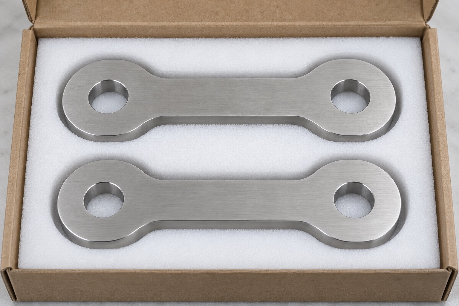
Finished links would be separated to protect useful faces, hole entries and narrow profile transitions without bending. Lot, revision, final process and acceptance status would accompany shipment; mechanical protection would not imply sterile supply. The production package would retain released geometry, mating interfaces, side clearance, movement and retaining definitions, material evidence and inspection methods. Authorized prototype changes would become revised documents. This representative workflow defines a traceable CNC project without inventing customer history, achieved tolerances or fatigue ratings, and without confusing a dimensionally accepted 316L link with a universally qualified complete medical equipment mechanism or safety system.
Manufacturer background reference: www.sandvik.coromant.com.
FAQ
Is this a real delivered two-hole linkage component?
No. It is a representative proposed manufacturing workflow with illustrative images. No customer delivery, manufactured specimen or actual measurement result is described. A real project needs controlled documents, material and production records, actual dimensional inspection and any separately required complete-mechanism qualification.
Does the example provide measured hole spacing?
No measured center distance or achieved tolerance is supplied. The actual drawing must define hole sizes and their relationship, and inspection must address the finished part with agreed references. An apparently symmetric image or two pins entering the holes is not a measurement record.
Are bearings, pins and retention hardware included?
No. The concept concerns the isolated flat link. Actual pivots, pins, spacers and retaining components belong to separately controlled assembly documents. Their selection and performance cannot be inferred from the rounded profile, two plain bores or a favorable trial movement.
Does the case demonstrate fatigue life or load capacity?
No. There is no manufactured specimen or complete-mechanism test here. Dimensional acceptance and easy hand movement do not establish load, fatigue, wear or retention. The actual assembly and operating conditions need separately defined evaluation and supporting evidence.
Can a hole be filed or an end thinned to remove binding?
Only through an authorized change with revised documents and relevant inspection. Review the full mating stack and both connections first. A manually modified trial link should not become an undocumented production master or a general proof that the service mechanism is suitable.
What should another order review?
Review mating members, pins, spacers, retention, center distance, hole sizes, thickness, profile, material and final process. Approved changes must enter controlled revisions rather than remain in an altered sample or performance claims copied from another medical equipment linkage.

tanghangyun@oemach.com