
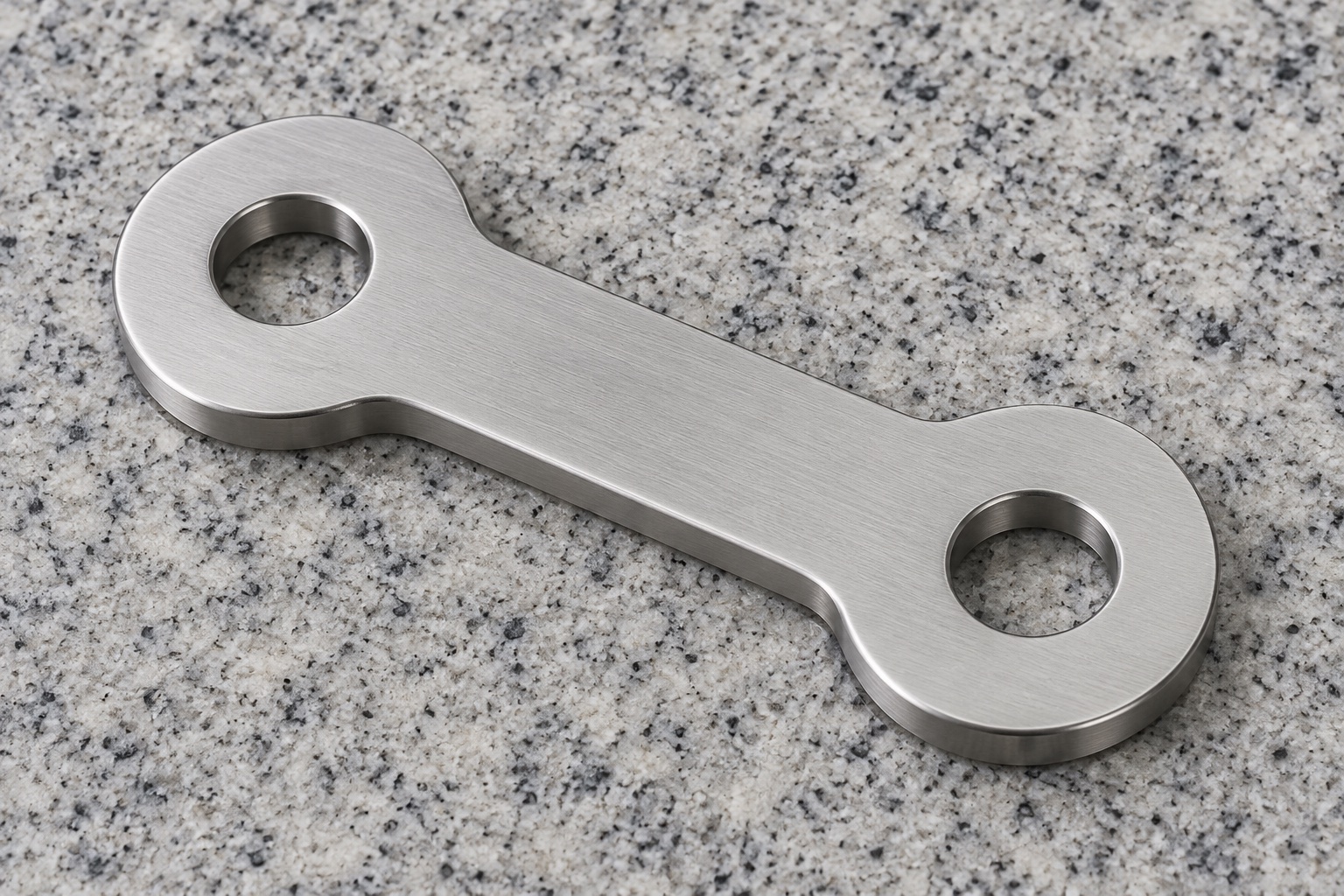
Define a component within the complete linkage
A service mechanism inside a medical laboratory instrument may connect two members through a flat machined tie link. The illustrative 316L component has two rounded end regions, a narrower connecting waist, uniform thickness and two plain equal-size through holes. There are no threads, bearings, inserts, bends or separate pins in the concept. No actual assembly or manufactured specimen is shown. The link is not an independently retained joint or a rated lifting component. Its role depends on the complete mechanism, actual mating members, support and permitted movement, which the equipment designer must define before manufacturing begins.

Identify both mating connections
Obtain the controlled link drawing and model, both pin or fastener interfaces, adjacent members and the actual equipment revision. Specify whether the holes provide clearance, location, pivoting or another defined mechanical role. Do not infer the connection from two convenient rods passing through a plate. The assembly may need separate retainers, spacers or bearing components, but none is established by the isolated illustration. Review installation order and access at each end. A nominal hole diameter is not enough to define both joints, the relative orientation of the surrounding members or the intended operation of the full service mechanism.
Control center distance independently of hole size
Define each bore and the required center-to-center relationship with an agreed reference scheme. Two individually acceptable diameters do not establish the spacing between them. Likewise, outside length or an apparently symmetric profile cannot replace the hole pattern requirement. Clarify how drawing and model express the relation, including any necessary geometric controls, before selecting the machining and inspection approach. The supplier should not open one hole, shift a center or file an entry simply to fit an unidentified assembly. Those changes require authorization because they may alter the mechanism's installation, movement and relationships to other references.
Review thickness and axial side clearance
Specify finished thickness, useful broad faces and relevant end contact areas. Review the actual mating stack, spacers, retainers and permitted side clearance together. A link that fits over two pins on a bench may still contact adjacent components or bind after retention hardware is installed. Do not add washers, reduce a face or locally thin an end without controlled approval. Any required axial location or movement belongs to the actual assembly definition. Component thickness and a favorable hand fit do not independently establish free operation, retention, wear behavior or safety of the complete medical equipment mechanism.
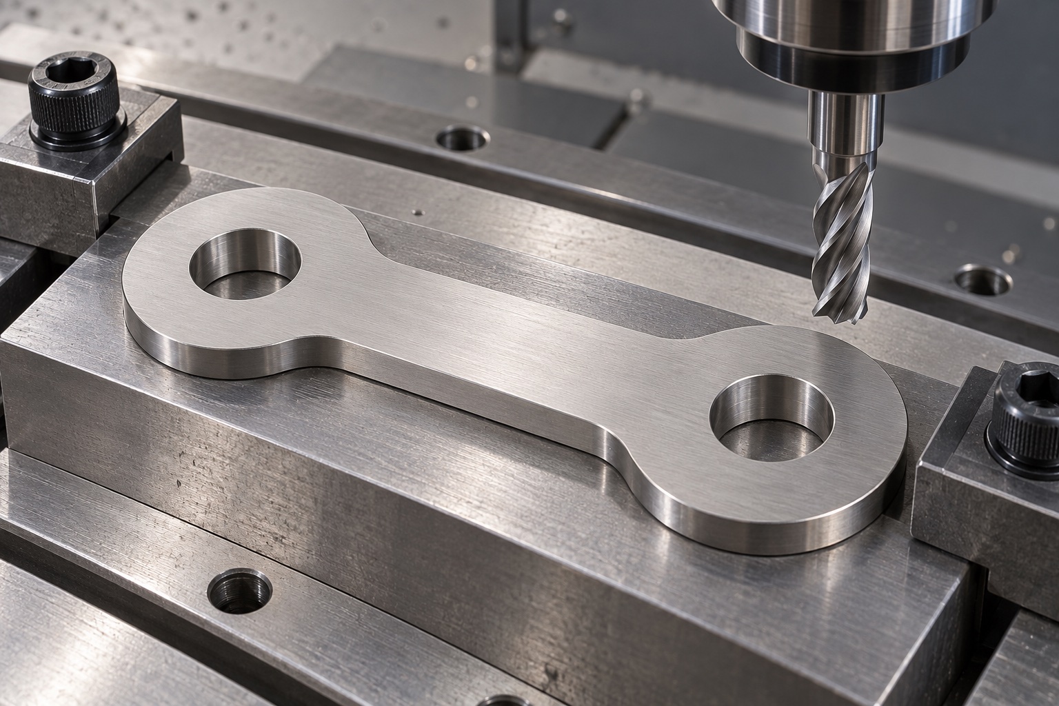
Define the end profiles and connecting waist
Specify the rounded end regions, remaining material around each hole, waist width, transition geometry and edge requirements. A convenient cutter path should not silently define the narrow section or blend radius. Clarify which outer areas provide clearance and whether any are useful contacts. Inspect the controlled profile rather than accept a familiar silhouette. No universal minimum section, load rating or fatigue margin is established here. Those require the real geometry, material condition, loading and separate application evaluation. Polishing a transition to make it look smoother should not become an undocumented change to the part's functional definition.
Specify 316L and the actual final process
Identify approved stock condition, form, lot evidence and purchased final treatment. The proposed 316L material does not automatically inherit a hardened linkage pin's or commercial tie rod's properties. Similar silver appearance is not proof of hardness, wear life, corrosion qualification or a load rating. Preserve identity through blank preparation, hole finishing and packing. Material documentation identifies stock within its scope; it does not establish validated cleaning, biological compatibility, sterile supply or medical equipment certification. Define relevant finished-component properties and evidence separately rather than transfer performance from an unrelated catalog assembly.
Plan hole and profile operations with related references
Review support, tool access, material sections and the route connecting useful faces, two bores and the exterior. Sandvik Coromant's drilling guidance identifies hole geometry, component material and holding as planning considerations; it is general process background, not an approved route for this link. Protect reference contacts and remove chips before reorientation. Intermediate checks can assist development, but final acceptance addresses the agreed delivered state. A plate forced flat by the fixture should not be accepted solely on that appearance. No universal drilling settings, clamping force or achieved center-distance tolerance is prescribed for every service linkage.
Finish bore exits and profile transitions deliberately
Inspect both hole mouths, through exits, face edges, waist transitions and end outlines for attached material or unintended sharp features. Apply approved edge breaks without removing useful bore length or contact area. Hand polishing until one pin moves more easily can conceal a bore or assembly discrepancy and requires review. Cleaning and final treatment should match the purchased scope. A smooth stainless surface does not establish low particles, low friction, validated disinfection or sterile delivery. If identification is needed, agree a marking location outside useful contacts and maintain the accepted finished geometry.
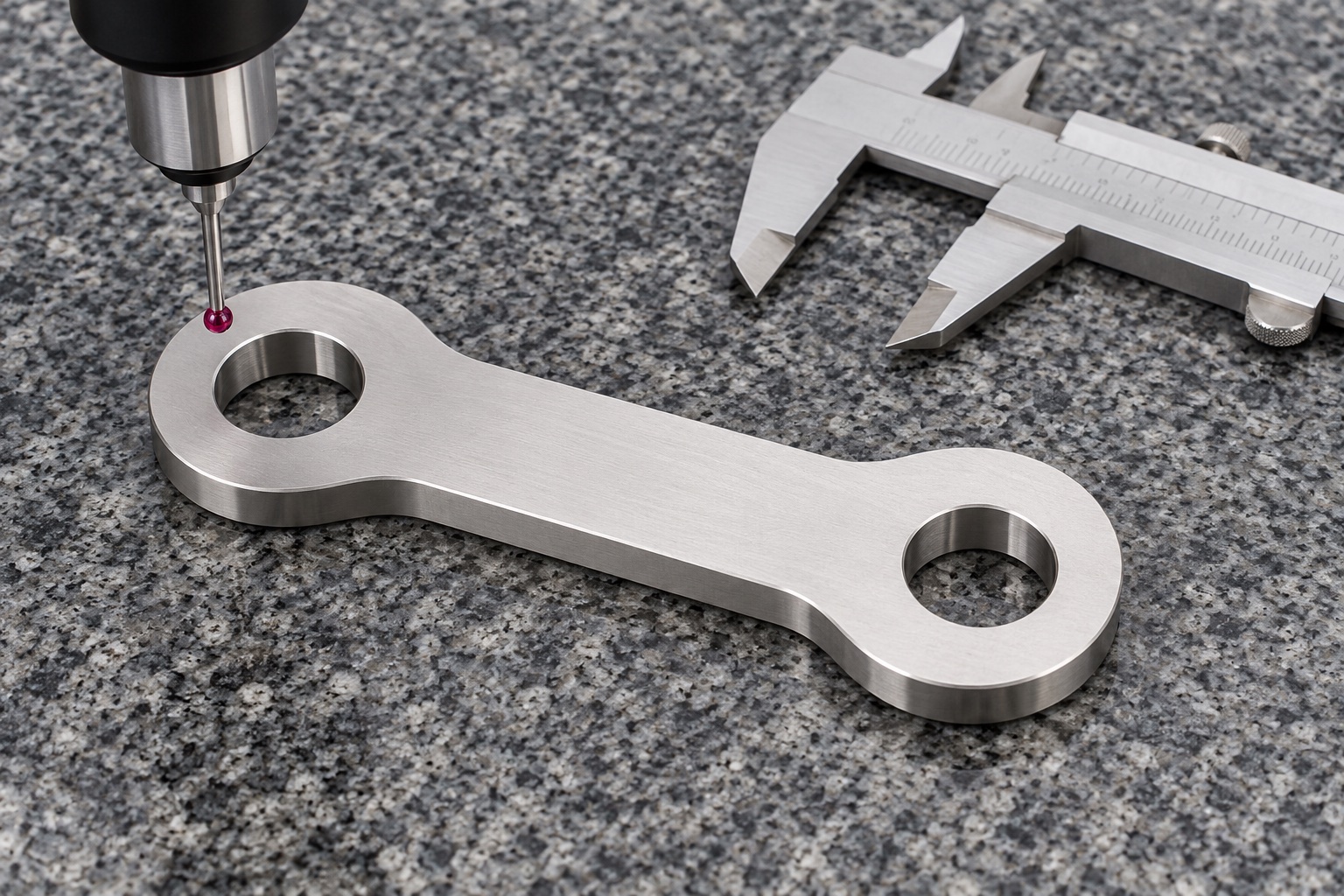
Inspect the related features in a defined condition
Map hole sizes, center distance, positions, finished thickness, faces and required profile relationships to accessible methods. Agree references, support and final processing before acceptance. A pin in each hole is not automatically a complete spacing check or a substitute for verifying both bores. Where a probe cannot reach a feature, resolve a suitable method instead of relying only on outside dimensions. A real report should identify revision, material lot, numbered characteristics and actual observations. A CMM or caliper image illustrates potential tools, not a passed dimensional result or qualified movement of the complete linkage.
Limit any optional mechanism observation
A separately agreed trial may examine installation, seating, intended movement, side clearance and access using identified link, pins, members and retention revisions. Record orientation and the actual assembly procedure. Favorable manual movement does not establish load capacity, fatigue life, wear, vibration behavior or retention during service. Those require separately defined evaluation of the complete actual mechanism and conditions. Keep trial pieces distinguishable from accepted production. Unexpected binding should trigger review before enlarging holes, reducing thickness or substituting hardware simply to obtain a successful demonstration or using one modified link as a universal production gauge.
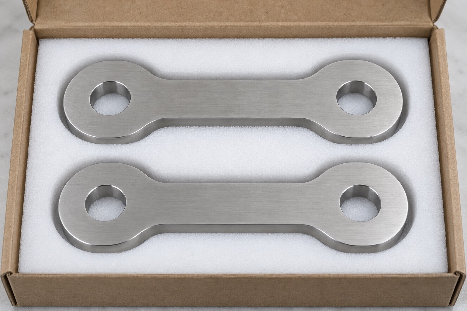
Protect faces, holes and variant identity during transport
Separate finished links so adjacent parts and loose hardware cannot strike useful faces, hole entries or narrow profile transitions. Supports should preserve the accepted state without bending the plate. Maintain lot, revision, final process and inspection status with the shipment. Mechanical protective packaging does not imply sterile supply. Receiving checks should distinguish links with similar silhouettes but different hole spacing, diameters, thickness or profile before installation. Keep the supplied component traceable to its approved revision while leaving the full instrument's independent movement, load, fatigue and service qualification to the responsible equipment team's controlled application procedures.
Prepare a linkage-specific manufacturing inquiry
Provide controlled geometry, both mating interfaces, actual pin or fastener arrangement, permitted motion, axial stack, side clearance, retention, material, final processes and inspection deliverables. Separate optional fitting from load, fatigue and complete-mechanism qualification. Review changes to mating members, pins, spacers or procedures before repeat manufacture. Approved prototype adjustments must become revised documents rather than a filed hole or thinned end retained as the next production reference. This establishes a traceable CNC component scope without inventing measured service performance or confusing a conforming flat tie link with a universally qualified medical equipment mechanism or safety system.
Manufacturer background reference: www.sandvik.coromant.com.
FAQ
Do two accepted hole diameters establish center distance?
No. Hole size and the relationship between hole centers are distinct requirements. The controlled drawing and inspection plan must identify both. A pair of pins entering the holes does not automatically verify the specified pattern, useful face relationships or complete mechanism alignment.
Does the illustrated link include pivots and retainers?
No. It is the isolated two-hole plate. Actual pins, bearings, spacers, fasteners and retaining components belong to separately controlled assembly documents. Their presence, selection and performance cannot be inferred from a familiar profile or two plain through holes.
Can thickness be reduced to remove binding?
Only through an authorized change and relevant revised inspection. Review the full mating stack, pin interfaces, side clearance and retention before altering the component. An easy hand trial after local thinning should not become an undocumented production requirement or proof of service suitability.
Does smooth manual motion prove fatigue or load performance?
No. It is a limited observation with identified parts. Load, fatigue, wear, vibration and retention need separately defined evaluation of the complete real mechanism and intended conditions. A dimensional report or an illustrative inspection image does not supply those results.
Is 316L automatically a hardened linkage-material substitute?
No. Material identity does not transfer another product's hardness, wear behavior, load rating or corrosion qualification. Define relevant properties and supporting evidence for the actual finished link and application. Similar appearance does not authorize a substitution or establish medical equipment certification.
What should a repeat-order review cover?
Review both mating members, pins, spacers, hole pattern, profile, thickness, side clearance, retaining arrangement, grade and final processing. Approved changes belong in controlled documents, not a manually modified link or performance assumptions copied from another medical equipment mechanism.

tanghangyun@oemach.com