
Define a mechanical coupling rather than a fluid fitting
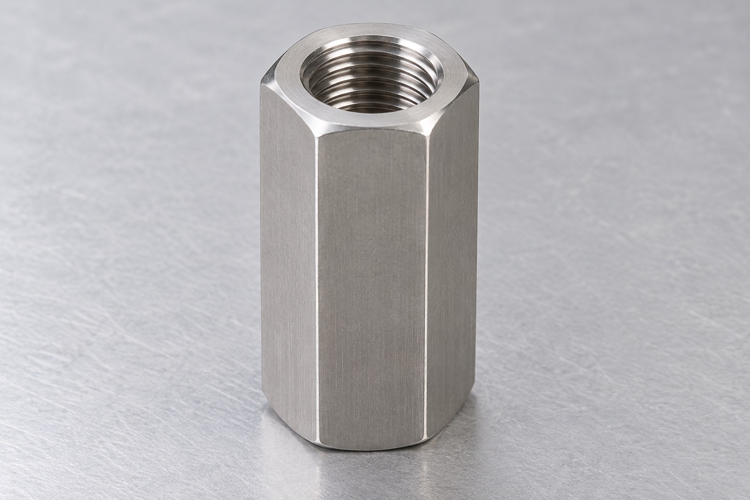
A service assembly inside medical laboratory equipment may join two threaded mechanical members with an elongated coupling nut. The illustrated concept has a straight hexagonal 316L stainless body, flat end faces and one coaxial internally threaded through bore. It has no external thread, cross hole, flange, insert or independent locking element. The proposed thread is continuous through the body; the image does not define its size or class. This article does not present a fluid seal, pressure fitting, implant or rated fastener product. The actual equipment designer must establish the connection and all relevant service requirements.

Specify the complete thread identity
Provide the thread system, nominal size, pitch, direction, tolerance requirements, useful length, entry treatment and any approved relief. Identify the mating members and their actual revisions. A familiar opening or outside hexagon does not establish a thread designation. Do not infer a class, mixed thread or tapered fitting from an illustration. Clarify drawing and model conflicts before manufacturing or ordering gauges. The proposed concept uses one ordinary continuous thread, not an assumed combination of opposite-handed threads. A coupling nut should not silently be treated as a turnbuckle or a universal adjustment mechanism for unrelated threaded components.
Allocate engagement from both ends
The assembly documents should define how far each mechanical member engages, the permitted final positions and any relevant end-face contact. Overall nut length is not automatically the effective engagement available to each member. Chamfers, incomplete threads, any allowed relief and the actual installed arrangement need consideration. Check whether the two member ends can meet or interfere inside the through bore before the intended assembly condition is reached. Do not invent a universal engagement value from the material or exterior length. Any required connection strength or service margin needs separately defined engineering and evidence for the actual assembly.
Define the role of the hexagonal exterior
Specify across-flats size, useful wrench-contact length, end treatment and required geometric relationships. Review tool access within the real medical instrument rather than only on a bench. A hexagon that accepts a wrench does not establish an assembly torque or prove that adjacent housings and cables remain clear during installation. The supplier should not reduce the flats, shorten the body or add a cross hole to solve an unidentified access problem. Such changes require authorized review. The actual equipment documents should distinguish tool clearance, mounting contact and any separately specified locking or retaining arrangement.
Relate the bore, end faces and outside references
Define which features establish manufacturing and inspection references and what relationships the drawing requires. A thread plug gauge does not independently verify end-face geometry, overall length, outside flats or every axis relationship. Identify the functional end contacts rather than assume that both faces are identical bearing or sealing surfaces. A correctly sized hexagon and a passing selected gauge check are not a complete component report. Clarify how the continuous bore and finished ends will be inspected after relevant operations, and keep these dimensional requirements separate from the strength and stability of the installed joint.
Keep 316L identity distinct from fastener ratings
Specify the approved stock condition, form, lot evidence and final processing. The proposed 316L material is not a universal substitute for every commercial coupling nut or fastener property class. Similar appearance does not transfer another product's proof load, hardness, wear behavior or corrosion qualification. Preserve identity through boring, threading, external finishing and dispatch. Where a particular surface condition or operating environment matters, define it explicitly and retain relevant evidence for the finished component. Material records alone do not establish validated cleaning, biological compatibility, sterile status or certification of the medical equipment connection.
Plan threading around access and chip removal
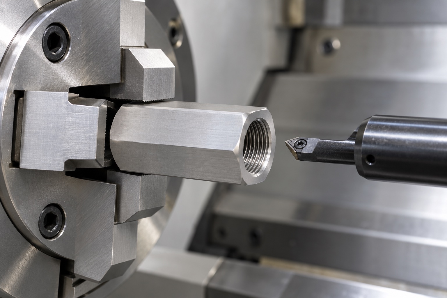
The route should review the through bore, tooling access, support, chip evacuation and reference transfer before finishing the internal thread. Sandvik Coromant identifies internal thread turning as sensitive to access, tool setup and chip control; that is general process background, not a validated recipe for this component. Select the actual method and tools against the approved thread and material. No universal cutting settings or guaranteed tolerance are supplied here. Avoid accepting a nut only because one mating rod can be forced through it. Finish and inspect the specified condition after all relevant operations and purchased treatments.
Control entries and useful thread boundaries
Inspect both bore entries, end chamfers, thread boundaries and exterior edges for attached material or unintended sharp features. Edge finishing should preserve the specified usable thread and useful end contacts. A long lead-in can alter the effective engagement available in a short connection, so it should not be added informally to improve hand assembly. Cleaning should remove process residues within the purchased scope without claiming validated disinfection or sterile delivery. Any approved final treatment that affects thread fit or surfaces belongs in the route and inspection plan rather than being assumed from the silver appearance.
Combine thread checks with the dimensional plan
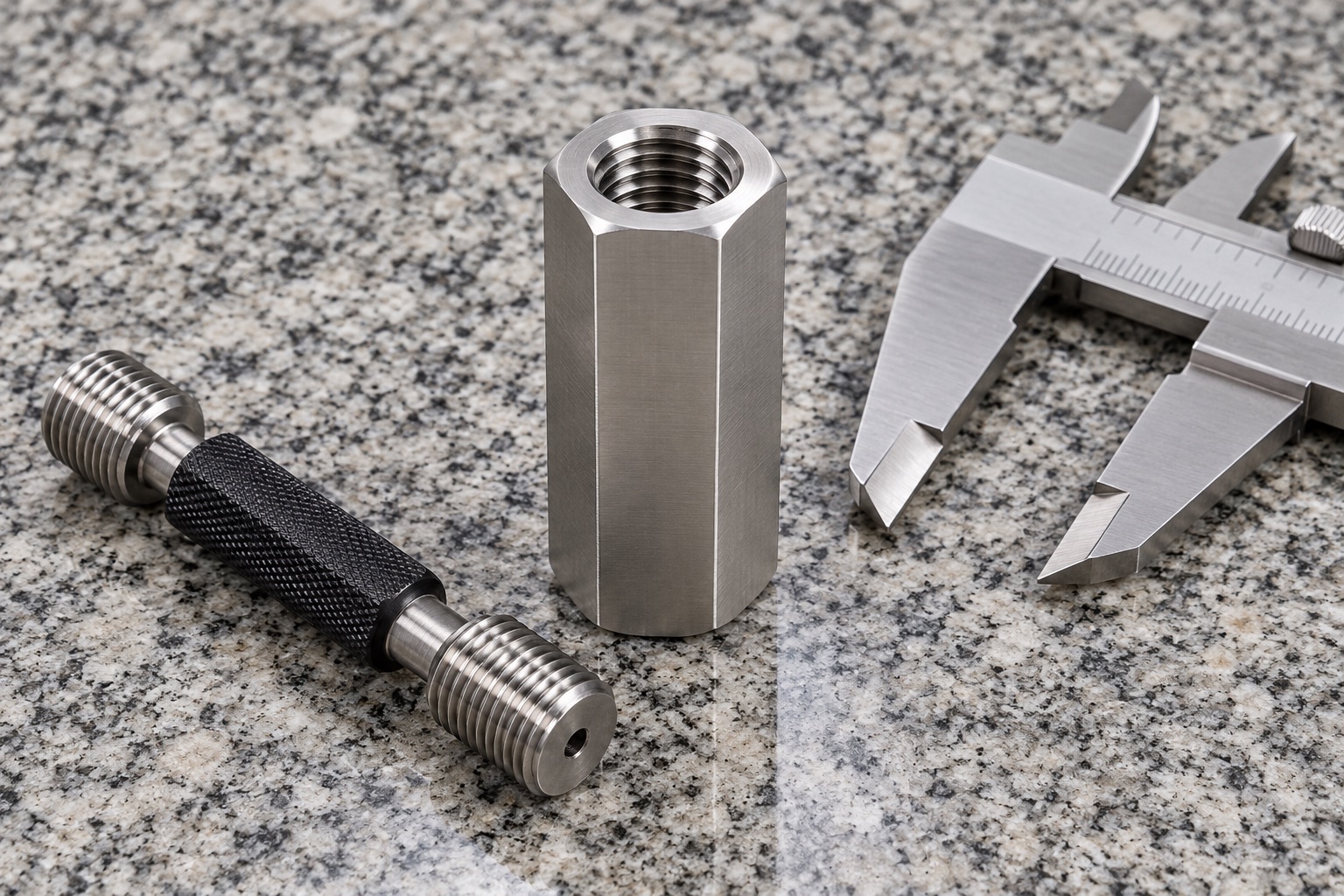
Agree the applicable gauges, methods, acceptance rules, access from each end and relevant finished condition. Gauge selection should follow the actual thread specification, not a nominally similar rod from another assembly. A thread plug check addresses its defined scope; it is not a measurement of every characteristic or a proof-load test. The complete plan should also cover length, flats, end faces and specified relationships. Keep actual observations linked to revision and material lot. A gauge photograph illustrates a possible method, not a passed result, achieved tolerance or rated performance of the finished nut.
Keep assembly observations separate from joint qualification
An optional trial may examine hand entry, specified engagement, member-end clearance, wrench access and intended seating using identified nut, members and assembly revisions. Record the procedure and any separately specified retention method. Easy hand assembly does not establish load capacity, resistance to loosening, wear behavior or stability in service. Those need separately defined evaluation of the actual joint and conditions. Unexpected resistance or early contact should trigger review, not additional force, informal thread polishing or substitution of another member merely to obtain a successful demonstration or a convenient production reference.
Protect bore entries and preserve variant identity
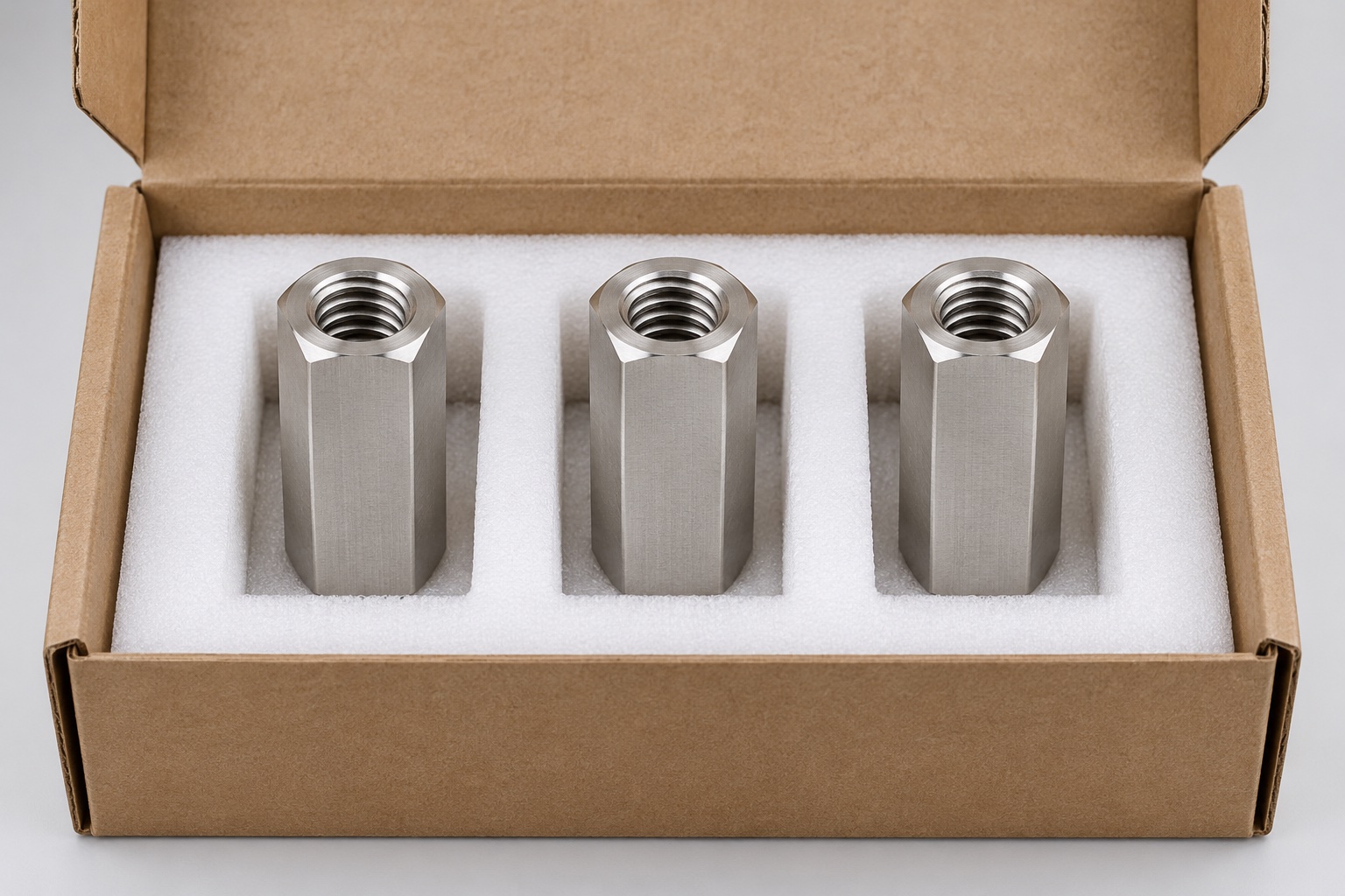
Separate finished nuts so loose metal parts cannot strike useful threads, ends or wrench faces. Keep chips and packaging debris out of the bore without implying that a protective cover creates sterile supply. Preserve material lot, revision, final process and inspection status with the shipment. Receiving checks should distinguish nuts with similar hexagonal outlines but different thread identities, handedness, useful lengths or end treatments before installation. Mechanical packaging protects the accepted component; it does not certify the connection, select a lubricant or authorize a service procedure for the complete medical instrument.
Submit a connection-specific manufacturing inquiry
Include controlled drawing and model, full thread designation, mating members, permitted engagement at both ends, end-face function, wrench envelope, retention method, material, final process and inspection deliverables. Separate optional assembly fitting from strength, loosening and complete-equipment qualification. Review changed rods, threaded studs, supports or service conditions before repeat manufacture. Approved prototype changes should become revised documents rather than an undocumented hand-fitted nut used as a universal gauge. This creates a traceable CNC connection scope without inventing measured fastener performance or confusing a dimensionally accepted 316L coupling nut with a qualified medical equipment joint.
Manufacturer background reference: www.sandvik.coromant.com.
FAQ
Does total nut length equal usable engagement on each side?
No. Entry treatment, incomplete threads, any approved relief and the actual positions of both members affect available engagement. Define the intended assembly and check member-end interference. No universal engagement or strength value is established by the illustrative outside length.
Is this a turnbuckle with opposite-handed threads?
No such design is shown. The concept has one continuous ordinary internal thread. A real order must specify its exact identity and direction. Do not infer opposite threads, tapered sealing threads or an adjustment function from a familiar coupling-nut outline.
Does a passing thread gauge establish load capacity?
No. A gauge addresses its defined thread acceptance scope. It does not independently establish proof load, resistance to loosening, member engagement, wrench access or full-joint suitability. Those requirements need separate definition and appropriate evidence for the actual assembled connection.
Does 316L transfer a commercial nut's property class?
No. The material name and a similar silver appearance do not establish another product's strength rating, hardness, wear life or corrosion qualification. Specify required finished-component properties and supporting evidence separately. The proposed material is not a universal substitution recommendation.
Can tight hand assembly be corrected by extra force?
Not as a substitute for resolving the cause. Review thread identity, finish, entries, contamination, engagement and member-end clearance using identified parts. Changes require authorization and appropriate inspection, rather than forcing one sample or informally polishing threads until an assembly demonstration succeeds.
What should another order review?
Review thread designation, mating members, engagement allocation, end contacts, wrench access, retention, grade and final processing. Incorporate approved changes into controlled revisions. Keep actual gauge and dimensional records separate from load or service claims transferred from another medical equipment joint.

tanghangyun@oemach.com