
Define support for a sealed sensor exterior
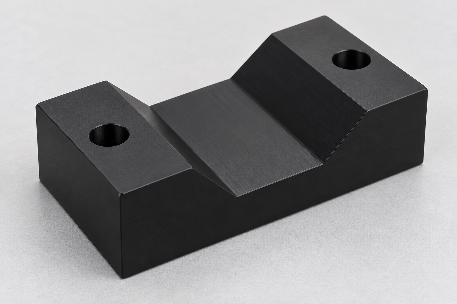
A medical laboratory instrument may use a machined polymer block beneath the exterior of a sealed cylindrical sensor body. The illustrated concept is a rectangular black POM-C block with one broad V-shaped channel and two plain mounting holes, one in each upper shoulder. The channel passes between opposite end faces. It is not a fluid path, sensor seal or complete retaining assembly. No actual sensor or manufactured installation is shown. The designer must define the permitted exterior contact, support orientation and separate axial, angular and retaining requirements before treating the block as a usable equipment component.

Identify the complete sensor envelope
Obtain the controlled block drawing, sensor housing specification, mounting base and actual device revision. Distinguish the permitted cylindrical contact band from labels, joints, cable exits, connectors, end caps and sensitive external features. A nominal body diameter is not a complete interface definition. Review approved variants and how the sensor enters and leaves the support. Do not assume that an externally similar sensor has the same allowed contacts or service access. The supplier should resolve missing interface information before machining rather than copy a convenient cylinder or infer the assembly from an isolated support-block illustration.
Specify the two V contact faces
Define the V angle, position, useful contact length and required face relationships relative to accepted references. The geometry should identify which regions support the housing and which provide clearance. A change in sensor diameter can change the supported center position, so the block must be reviewed with the actual permitted housing range and equipment coordinate requirements. Do not claim a universal center height from the V shape alone. A caliper measuring the opening at the top cannot verify both sloping faces, their intersection or their relationship to the mounting base and sensor interface.
Keep the root separate from useful contact
Specify the bottom relief and edge transitions rather than allowing an arbitrary cutter shape to define them. Clarify whether the cylindrical housing should contact the intended V faces without touching the root or neighboring shoulders. Root clearance and contact acceptance require the actual geometry, not a photograph that appears to contain a cylinder. The supplier should not deepen the groove or polish a face until an unidentified sensor sits conveniently. Such changes need controlled review because they may alter support height, contact location and the remaining section of the block even when the external rectangular outline is unchanged.
Define mounting without assuming retention
Give the two plain through holes their approved sizes, positions and edge requirements. Identify the useful bottom support face and any other mounting references. Clearance fasteners should not silently become precision locators. The complete instrument may require separate axial stops, angular references or retaining hardware, but none is established by this isolated block. Specify any such features in the actual assembly documents rather than adding them during machining. A sensor resting in a V under gravity does not by itself demonstrate resistance to lifting, rotation, movement, vibration or loss of alignment during service.
Select the exact polymer and finished condition
Identify the approved black POM-C grade, stock form, condition, lot evidence and purchased final process. Do not substitute another acetal or black polymer solely because its appearance is similar. Ensinger's POM machining information provides general material-processing background, not approval of this sensor interface or a transfer of medical qualification. Review the actual environment and the responsible team's permitted contact and cleaning conditions. Material identity alone does not establish electrical insulation, sensor accuracy, disinfectant compatibility, low particles or sterile status. Any required finished-component property needs its own defined scope and supporting evidence.
Support the block through machining and reorientation
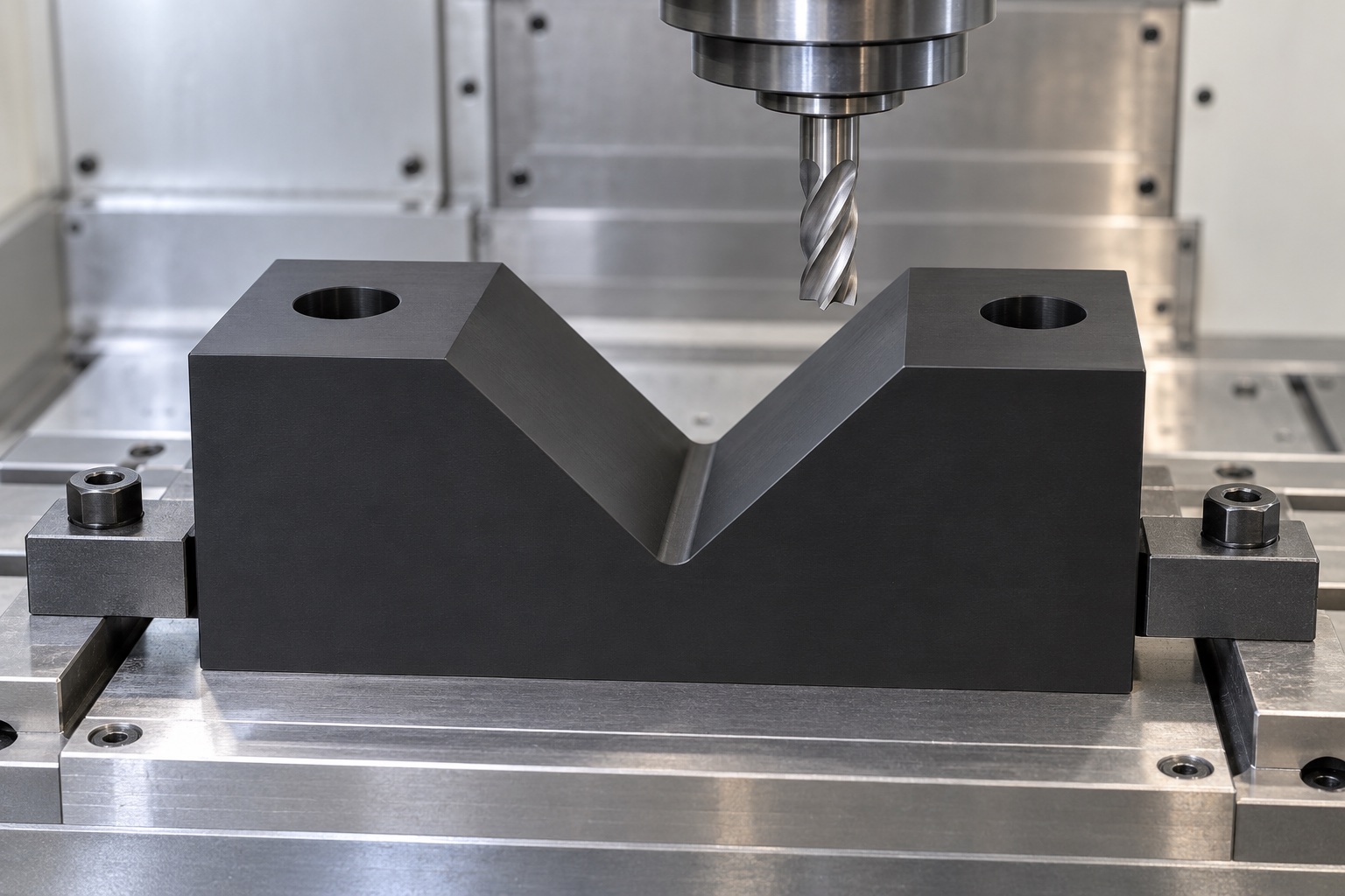
Plan how the bottom reference, V faces and mounting holes remain related throughout the route. Protect useful contacts from concentrated clamp pressure and embedded chips. Review tool access and the material remaining below the channel and around the shoulder holes. Intermediate checks can guide process development, but a heavily constrained component should not be accepted only because its fixture produces a favorable shape. Any conditioning or intermediate treatment belongs to an agreed material-specific plan. Remove chips from references after reorientation and inspect the delivered condition after relevant operations rather than relying on a raw or fixture-imposed geometry.
Finish the channel without rounding away its definition
Inspect V entries, root transitions, mounting-hole exits and exterior edges for attached material or unwanted sharp features. Apply controlled edge breaks while preserving the useful face lengths and specified root clearance. Hand sanding until one housing rocks less can conceal a reference or interface problem. Cleaning should match the purchased scope and preserve the accepted grade and geometry. A smooth black appearance does not demonstrate low friction, absence of sensor-shell damage or validated disinfection. If exterior marking is needed, agree its location outside useful contact rather than add an unapproved feature to the sensor support region.
Use inspection methods that resolve the contact geometry
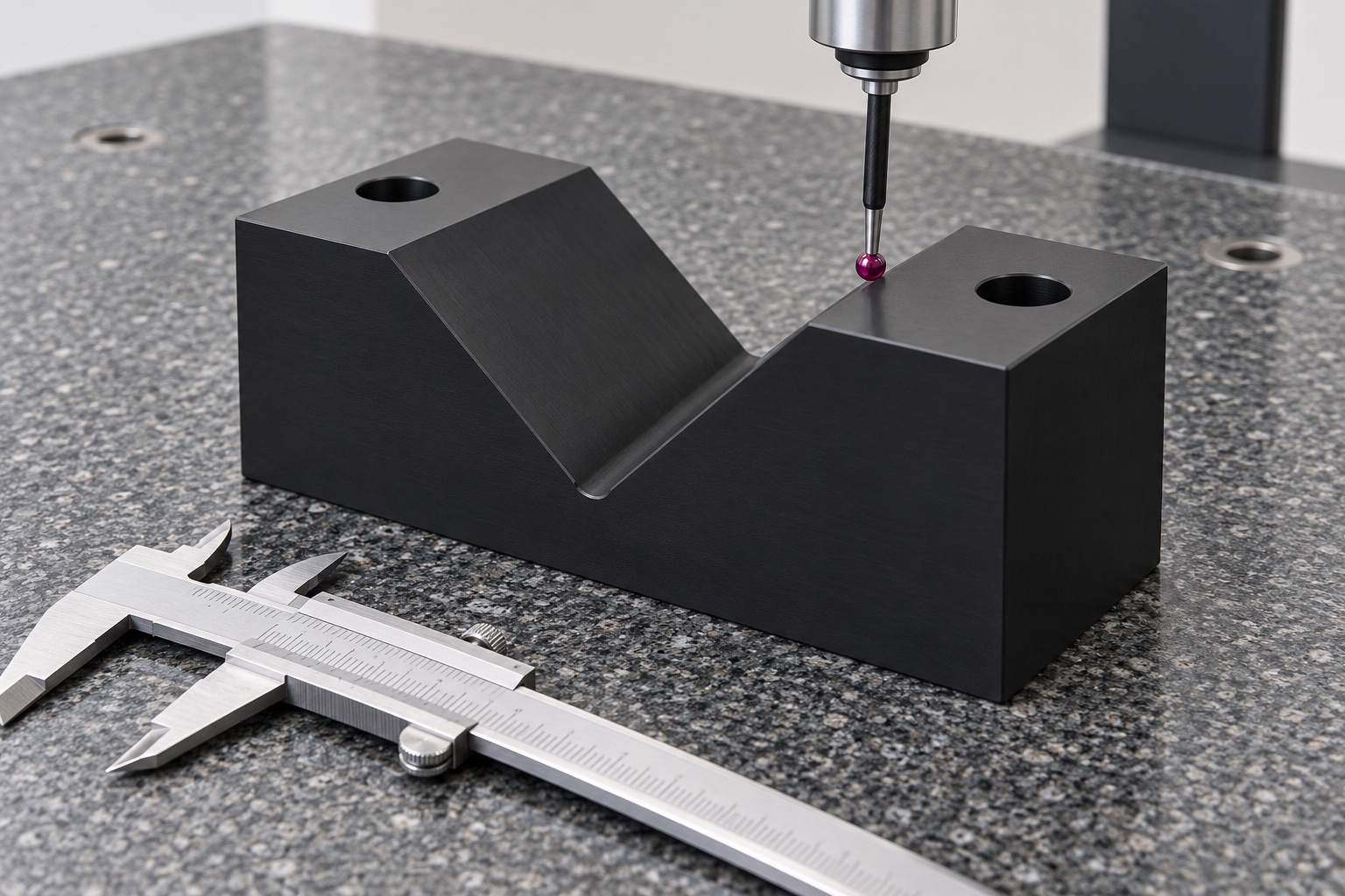
Map V faces, angle, position, bottom reference, root, holes and specified relationships to suitable accessible methods. Define support, contact pressure, references and final condition before inspection. Outside dimensions alone do not establish the sensor axis or intended contact arrangement. A cylindrical check piece may help observe selected contacts but is not a complete substitute for the geometric inspection plan. A real report should identify drawing revision, lot, numbered features and actual observations. Illustrative CMM or caliper scenes show potential tools, not measured angular conformity, achieved center height or qualified sensor alignment.
Limit an optional sensor seating observation
A separately agreed trial may examine entry, intended housing contacts, cable clearance, access and seating with identified block, sensor, base and hardware revisions. Record orientation and the actual retaining arrangement. Favorable static seating does not establish axial location, angular retention, vibration behavior, sensor calibration or measurement accuracy. Those require separately defined evaluation of the complete actual instrument. Keep trial blocks separate from accepted production. Unexpected contact with a label, connector or housing joint should trigger review before altering the groove or substituting another sensor merely to obtain an apparently successful installation photograph.
Protect useful faces and variant identity
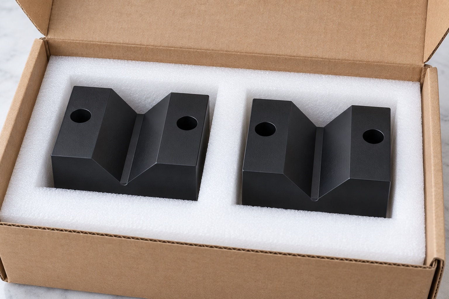
Separate finished blocks in supports that prevent adjacent parts and loose hardware from striking the V faces, root or mounting references. Avoid packaging pressure that distorts the accepted geometry. Preserve grade, lot, revision, final process and inspection status with the shipment. Mechanical protection does not establish sterile delivery or validated cleaning. Receiving checks should distinguish blocks with similar outlines but different angles, contact lengths, root clearances or hole patterns. Identify the actual approved sensor variant before installation, leaving the full sensor system's calibration, retention and service evaluation to the equipment team and its separately controlled procedures.
Provide a sensor-interface inquiry package
Include the controlled block model and drawing, housing contact band, approved sensor variants, V definition, root clearance, mounting and retaining arrangement, base references, material, final state and inspection deliverables. Separate optional seating observations from instrument alignment, measurement and application qualification. Review changed housings, connectors, labels, base geometry or cleaning scope before repeating manufacture. Approved prototype adjustments should become revised documents rather than an undocumented hand-sanded master. This defines a traceable polymer-machining project without inventing sensor performance or treating one dimensionally accepted V support as a universal medical sensor holder and validated measurement system.
Manufacturer background reference: www.ensingerplastics.com.
FAQ
Does the V block hold the sensor in every direction?
No. It provides only the contacts defined by the actual design. Axial stops, angular control and retention must be specified separately where needed. A housing resting in the groove does not demonstrate resistance to lifting, rotation, vibration or movement in service.
Can one nominal sensor diameter define the interface?
No. Review the permitted contact band, body variation, joints, labels, cable exit and connector envelope. Different diameters can change the supported center position. The full equipment interface must be reviewed rather than transferring fit or alignment assumptions from one visually similar sensor.
May the cylindrical housing touch the groove root?
That depends on the approved design. Define useful V contacts and root clearance explicitly. The supplier should not deepen or polish the groove informally to make a sample sit better; changes can alter height, contact and remaining material and require controlled review.
Does a round check piece verify the entire block?
Not independently. It may support selected observations within an agreed method. The actual inspection plan must address V geometry, root, mounting holes, useful faces and required relationships in the finished state. A seating photograph is not a complete dimensional report.
Does black POM-C establish electrical or cleaning performance?
No. Material identity and appearance do not prove electrical insulation, disinfectant compatibility, low particles or validated cleaning of the finished component. Define required properties and evidence for the actual grade, geometry, sensor interface and instrument environment instead of inferring them from color.
What should a repeat-order review include?
Review sensor housing and contact bands, connectors, labels, V geometry, root clearance, mounting base, retention, grade and final processing. Approved changes belong in controlled revisions, not in a hand-sanded sample or a calibration claim transferred from another instrument.

tanghangyun@oemach.com