
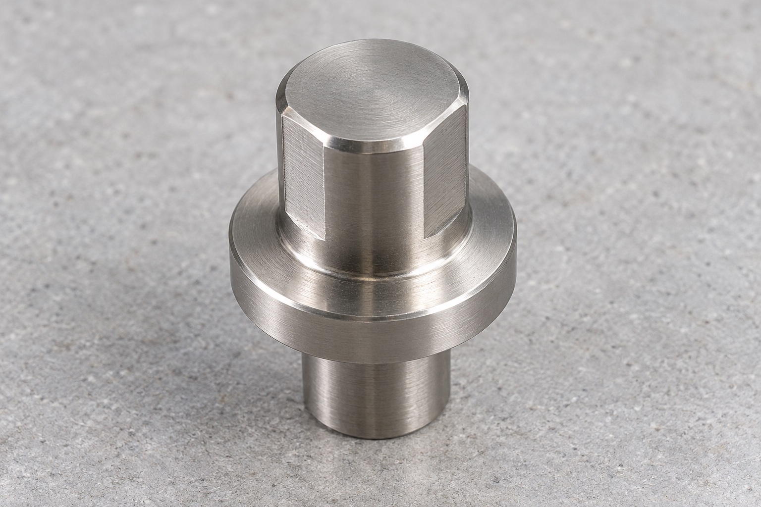
Define a directional locating interface
A service fixture or removable module in medical laboratory equipment may use a relieved locating pin alongside other controlled references. The illustrative stainless component has a plain cylindrical mounting stem, integral flange and short locating head with opposed relief surfaces and remaining curved contacts. It is not a fully round locating head in this concept. No actual assembly or measured result is shown. The shape does not independently establish complete position, repeatability, retention or load capacity. The equipment designer must define which directions each contact controls and how the actual assembly is supported and held.

Identify the full locating scheme
Obtain the controlled pin model and drawing, mating feature, supporting surface, other locators and retention arrangement. Carr Lane explains the general principle of a relieved diamond pin paired with a round locator to avoid redundant location in a particular direction. That is background, not approval of this custom geometry, material or fixture. Do not assume that one relieved pin establishes every degree of freedom. The actual scheme must identify useful contacts and clearances, which part is removable and the installation orientation. Clarify the reference intent before selecting turning, milling or inspection operations for a real order.
Specify contacts and relief separately
The remaining curved surfaces and the relieved regions have different roles. Define useful head size, relief width or depth, axial contact length, lead-in and allowed transitions relative to the accepted references. A caliper measurement across the relief does not verify the remaining locating contacts. Conversely, a head fitting one hole does not establish the intended directional clearance. Do not polish a contact into a relief or add another flat merely to make insertion easier. Any adjustment requires authorization and revised documents so later production preserves the actual locating intent rather than the appearance of a modified sample.
Control orientation in the actual fixture
A relieved head must have a defined installed orientation relative to the mating feature and other references. A plain cylindrical mounting stem alone does not indicate how angular position is set or maintained. Identify the approved installation method or separate orientation feature without assuming an unshown key, screw or mark. If the drawing does not define the required relationship, clarify it before manufacture. An illustration standing upright on a bench does not establish fixture orientation. A pin that enters easily after being rotated may indicate that the actual contact and clearance arrangement needs controlled review, not that the whole assembly is qualified.
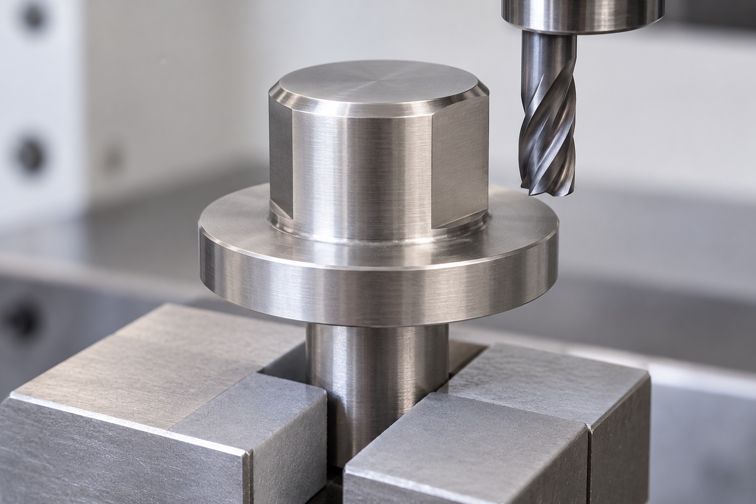
Relate mounting stem and flange to the head
Specify mounting stem geometry, useful flange face, axial positions and required relationships to the locating surfaces. Identify what establishes the inspection reference and distinguish it from a convenient holding diameter. The flange is not automatically a seal or a clamping feature. The equipment assembly should define whether it seats against a support and how the pin is retained. A correct stem diameter alone cannot verify the locating head's relationship to the fixture. The supplier should not shorten the stem or change its fit to accommodate an unidentified support without an authorized design and inspection review.
Keep stainless identity and application properties distinct
State the approved 316L stock condition, form, lot evidence and purchased final processing. The material is a proposed component choice, not a claim that it is suitable for every wear or loading condition. Maintain traceability through turning, head relief and shipment. Similar silver appearance does not authorize another alloy or transfer the properties of a hardened catalog locator. Material identity does not establish wear life, hardness, corrosion performance, biological compatibility or sterile supply. Relevant properties require separately defined requirements and actual evidence for the complete finished component and the real equipment-side locating application.
Preserve references across turning and milling
Plan how the stem, flange and locating head remain related when the part moves from turning to relief machining. Protect useful contacts and remove chips before reorientation. Review support, tool access and remaining sections before finishing. The supplier should not accept a part solely because the fixture imposes a favorable shape or angular reading. Intermediate measurements can help process development, but final acceptance addresses the defined delivered condition after relevant operations. No universal machine sequence, cutting settings or achieved positional tolerance is prescribed here. Approved changes affecting references belong in the controlled manufacturing and inspection scope.
Finish lead-ins without removing useful contact
Inspect top lead-in, relief transitions, flange edges and stem ends for attached material or unwanted sharp features. Apply released edge requirements without reducing useful locating length or widening directional clearance beyond the drawing. Hand polishing until one unidentified mating part enters can conceal an interface issue. Cleaning and final treatment should preserve accepted geometry. A smooth stainless surface does not prove low particles, galling resistance, validated cleaning or sterile delivery. Keep visual condition distinct from dimensional acceptance and from the equipment team's separate assessment of repeated insertion, wear and maintenance under its actual service environment.
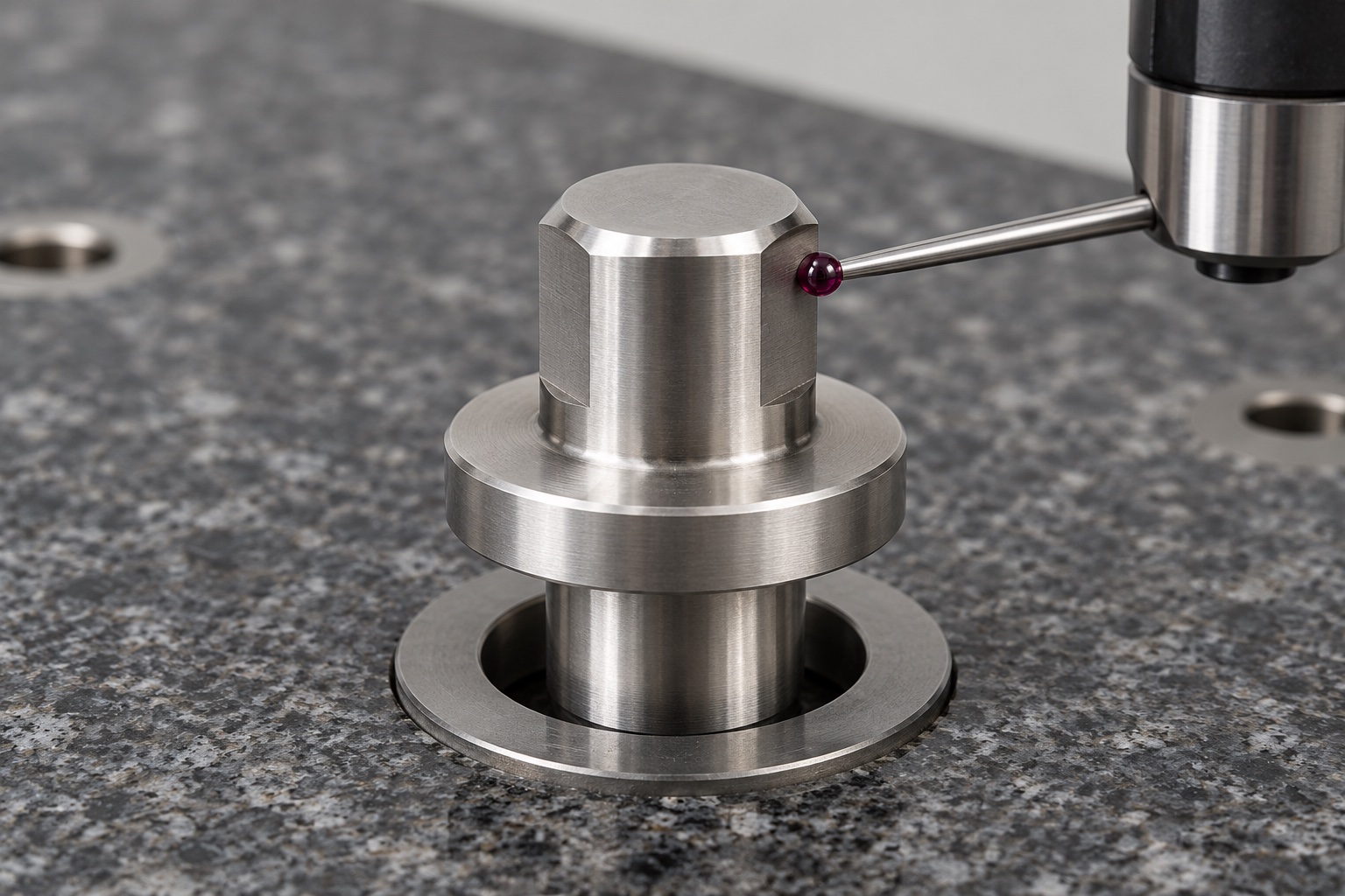
Inspect form, relationship and orientation requirements
The inspection plan should identify methods for mounting stem, flange face, useful locating contacts, relief geometry, axial positions and any controlled angular relationship. Specify support, reference establishment and final condition. A micrometer or caliper check addresses selected sizes, not every form or contact relationship. A CMM illustration is one possible arrangement, not a measured result or guaranteed repeatability. Clarify inaccessible regions before acceptance. A real report should preserve numbered characteristics, drawing revision, material lot and observations, keeping head geometry separate from optional fitting with an identified mating component and the complete fixture's qualification.
Separate entry trials from locating repeatability
An optional assembly observation may examine entry, seating, useful contacts and intended clearance with identified pin, mating part, other locators, support and retention hardware. Record the installed orientation and actual procedure. Favorable hand insertion does not establish repeatability, absence of binding across all approved variants, load capacity or retention during service. Those need separately defined evaluation of the complete scheme and operating conditions. Trial pins should remain distinguishable from accepted production. Unexpected force or contact should trigger review before altering reliefs or rotating the pin informally to obtain a successful demonstration.
Protect contacts and preserve orientation identity
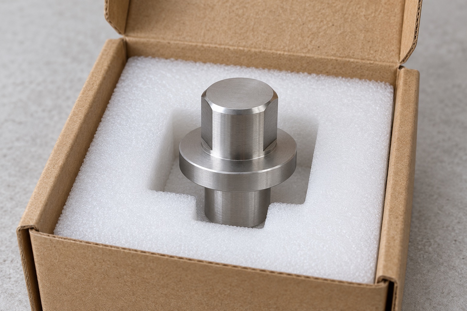
Separate finished pins so hard parts cannot strike the useful head surfaces, relief edges, flange or mounting stem. Support and restraint should avoid abrasive contact and preserve the accepted condition. Mechanical packing does not imply sterile delivery. Keep material lot, revision, final process and inspection identity with the shipment. Where orientation identification is required, its method and permitted marking location should be approved rather than added on a useful contact. Receiving staff must distinguish full-round and relieved variants before installing them into the actual fixture and performing independent locating, retention, wear or maintenance evaluation.
Make the inquiry locating-scheme specific
Provide controlled drawing and model, mating feature, other locators and support, useful contacts and directional clearances, mounting and orientation method, retention, material, final process and inspection deliverables. Identify optional fitting separately from repeatability, wear and complete-fixture qualification. Review changed mating holes, supports, reference arrangements or installation methods before repeating manufacture. Approved prototype adjustments should enter revised documents instead of keeping a hand-polished pin as the next production gauge. This defines a traceable turning and milling scope without inventing measured positioning performance or confusing one accepted locator with a qualified medical equipment positioning system.
Manufacturer background reference: www.carrlane.com.
FAQ
Does one relieved pin locate every direction?
No. The actual fixture must define all supporting, locating and retaining features. Relief provides intended clearance in a specified direction, not a complete locating scheme. The responsible designer must define and qualify the actual contact arrangement and installation.
Is a relieved head interchangeable with a round pin?
Not automatically. Their useful contacts and clearances differ. Replacing one with the other can change the locating scheme. Use released geometry and review the mating feature, other references and orientation instead of substituting a familiar-looking catalog item.
Does the plain mounting stem define angular orientation?
Not by itself. The assembly must identify how the relieved head is oriented and maintained. Do not infer an unshown key, screw or marking. Clarify missing requirements before machining or installation rather than rotate the pin informally until a sample fits.
Does a fit trial establish repeatability?
No. It is a limited observation with identified components and orientation. Repeatability, binding across variants, wear, load and retention need separately defined evaluation of the complete actual fixture. No achieved positioning result is demonstrated by an illustrative inspection image.
Does 316L imply the properties of a hardened locator?
No. Material identity does not transfer another product's hardness, wear life or load performance. Specify required finished-component properties and evidence separately. This proposed material is not a universal recommendation for every locating or repeated-insertion application.
What should repeat-order review include?
Review mating geometry, other locators, support, contact and relief requirements, orientation, mounting and retention, material and final processes. Preserve approved revisions rather than copy a hand-polished pin or transfer measured results from another medical equipment fixture.

tanghangyun@oemach.com