
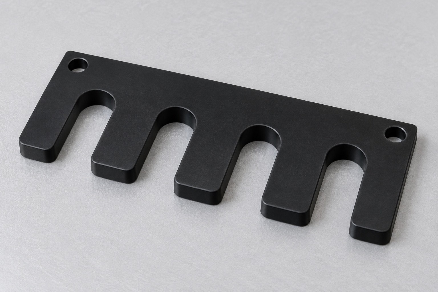
Define contact with the closed tube exterior
A medical laboratory handling station may use a machined positioning comb to provide defined external guidance for closed tubes. This article considers a black POM-C plate with four open-ended U slots along one long edge and two plain mounting holes in the rear strip. It is not a fluid path, cap opener or centrifuge holder in this concept. No tube, specimen or actual manufactured assembly is shown. The geometry does not establish tube retention, transport safety, sample integrity, assay performance or validated cleaning. The equipment team must define the actual tube family, orientation and intended handling operation.

Identify the tube family and supporting arrangement
Obtain the controlled comb drawing and model, closed-tube specifications, underlying support and actual mounting hardware. Identify the tube body region that may contact the slots and distinguish it from caps, labels and tapered regions. The comb alone should not be assumed to support tube weight or prevent vertical escape. Specify any additional base, cover or retention components in the released assembly. A nominal tube diameter is insufficient when approved variants have different external features. Clarify how tubes enter and leave before asking the supplier to manufacture a pattern copied from a photograph.
Specify slots as profiles, not circles
Each U slot needs width, useful depth, root profile, entry treatment and position relative to accepted references. An open slot is different from a closed bore: one pin fitting near the root does not verify the entire entry and contact path. Define which portions provide guidance and which are clearances. The supplier must not deepen a root, flare an entry or thin a finger to fit one unidentified tube. Model and drawing conflicts should be resolved before finishing. The illustration is not a universal tube size, approved pitch or statement that every commercially available sample tube will fit.
Relate slot pitch to the complete station
Specify spacing between slots and its relationship to rear mounting holes and useful support faces. Equal visual spacing is not measured evidence of the required pattern. The actual station may also depend on its base, transport path, gripper access or other separately controlled interfaces. A comb bolting to a panel does not establish every tube center in the equipment coordinate system. Avoid using clearance fasteners as unqualified precision locators. If the design needs dowels or adjustable features, identify them explicitly and agree inspection references rather than adding them informally after one trial appears misaligned.
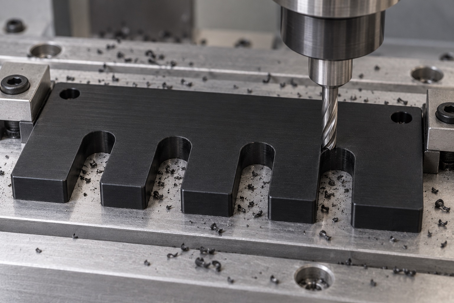
Keep the polymer grade explicit
Specify the approved black POM-C grade, stock form, lot evidence and purchased final condition. POM-C and other acetal variants are not interchangeable merely because they look black. Ensinger's POM machining information is general material-processing background, not approval of this tube-contact concept or a transfer of medical qualification. Preserve material identity through blank preparation and machining of the fingers. The supplier should not infer compatibility with disinfectants, measured wear or biological properties from a stock description. Relevant material and finished-component requirements need their own scope and evidence for the actual laboratory environment.
Support fingers during slot machining
Review remaining finger sections, rear strip, holding contacts and operation sequence before cutting the open slots. Protect useful surfaces from clamp pressure and embedded chips. Select tooling and chip removal for the approved stock and geometry without claiming universal cutting settings. A thin finger should not pass acceptance solely because the fixture forces it into a favorable position. Any conditioning or intermediate treatment belongs to an agreed material-specific process plan. After reorientation, remove chips from references and preserve the relationship between slots, mounting pattern and support faces in the actual released final component condition.
Finish entries without changing contact
Inspect slot mouths, roots, finger ends, mounting-hole exits and outer corners for attached material or unwanted sharp features. Apply released edge breaks while preserving specified pitch and useful guidance surfaces. Hand sanding until one tube slides through is not a substitute for an authorized profile change. Cleaning should match the purchased scope. A smooth black surface does not establish low particle generation, low friction, validated disinfection or sterile delivery. Where tube labels or external surfaces matter, the responsible equipment team should define relevant contact limits and evaluations rather than infer acceptable handling from appearance.
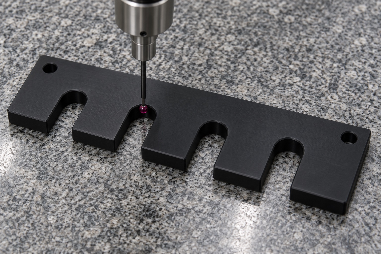
Use appropriate dimensional methods
Map slot width, profile, depth, pitch, rear holes, useful faces and required geometric relationships to accessible methods. Agree support, reference establishment and final condition before inspection. Avoid measurement contacts that significantly deform a finger. A caliper or gauge observation addresses its specified characteristics, not the entire station. A CMM picture is an illustrative setup, not a measured tolerance or verified pattern. Retain numbered characteristics, revision, material lot and actual observations in the report. If profile access is limited, agree a suitable method rather than accept the comb from outside dimensions and one tube-fitting demonstration alone.
Limit optional tube-fitting observations
An optional trial may examine entry, intended body contact, spacing and access using identified comb, closed tubes, base and mounting hardware. Record tube and equipment revisions and the actual installation method. A favorable static fit does not establish retention during motion, resistance to tipping, absence of tube damage or suitability for biological specimen handling. Those require separately defined evaluation of the complete station under actual conditions. Keep trial components separate from accepted production. Unexpected contact should enter review before altering slots or substituting another tube simply to obtain a favorable demonstration.
Do not infer assay or contamination performance
The comb is an equipment-side mechanical component in this scope. Its material identity and dimensional report do not demonstrate specimen integrity, diagnostic accuracy, cross-contamination prevention or validated cleaning. The actual application may impose additional requirements, but the supplier should not invent them or claim compliance without evidence. Define the responsible parties, procedures and acceptance records separately from the CNC drawing. A clean-looking part or protective foam tray is not a sterile supply claim. Keep any approved marking outside useful contacts and preserve the identity of tube variants and prototype pieces during process development.
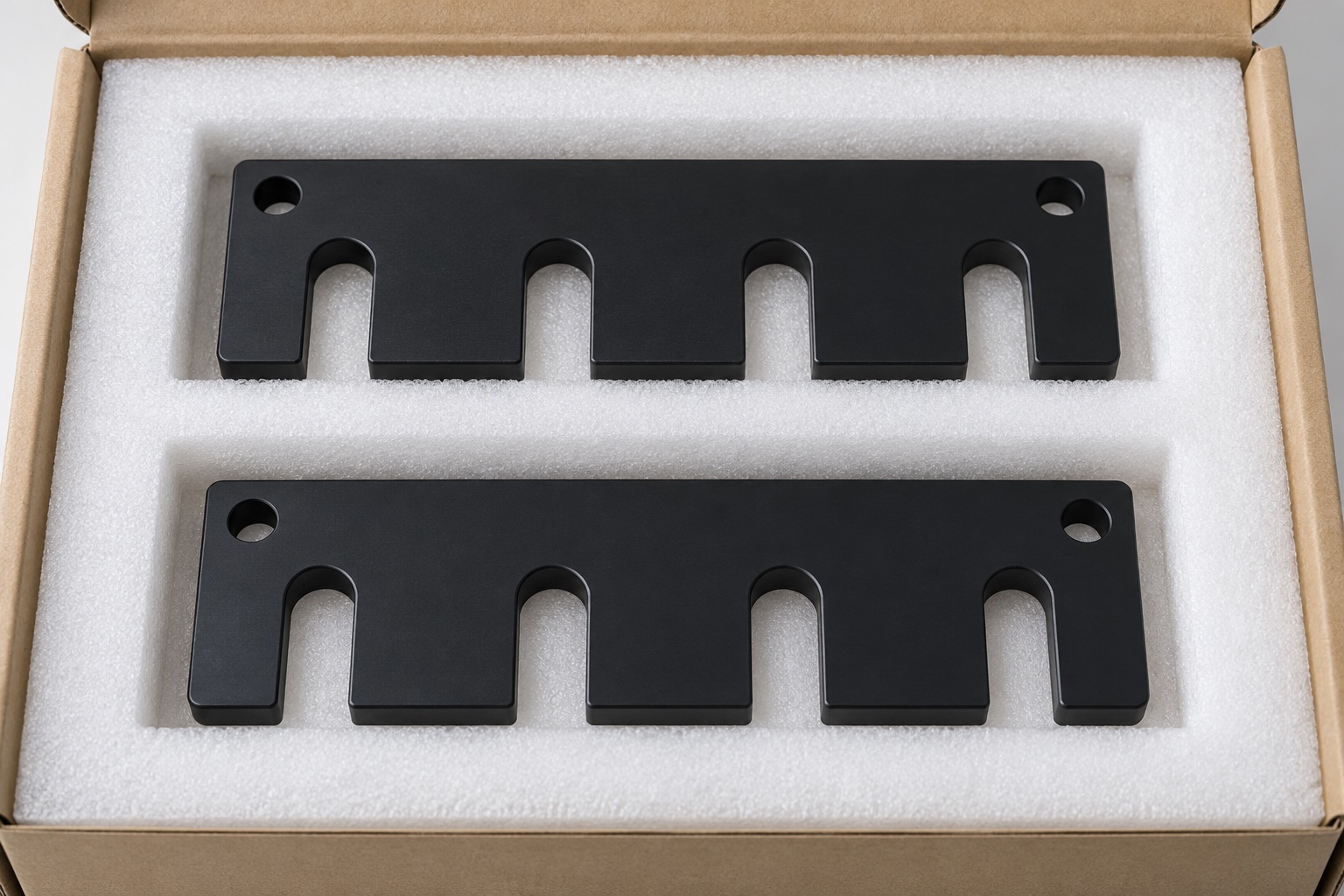
Protect fingers and roots during shipment
Separate finished combs so neighboring parts and loose fasteners cannot strike slot mouths or embed in contact faces. Pocket size and restraint must avoid bending fingers or compressing the rear strip. Preserve grade, lot, revision, final process and inspection status with the shipment. Mechanical transit protection does not mean sterile delivery. Receiving checks should distinguish similar combs with changed pitch, width, depth or mounting holes before installation. Maintain the link to the actual accepted drawing and equipment variant before the laboratory team performs its independent tube-handling, cleaning and application-specific evaluations.
Provide a tube-specific inquiry package
Include controlled geometry, exact closed-tube family, allowed contact region, entry and exit path, supporting base, mounting and locating method, polymer grade, final condition and inspection deliverables. Identify optional fit observations separately from retention, specimen-handling and complete-station qualification. Review changed tube suppliers, labels, caps, grippers or support arrangements before repeating manufacture. Approved adjustments must enter revised documents rather than leave a hand-sanded comb as the next production reference. This defines a traceable CNC project without inventing measured handling performance or treating a dimensionally accepted open-slot plate as a universally validated medical laboratory tube carrier.
Manufacturer background reference: www.ensingerplastics.com.
FAQ
Does the comb itself support and retain every tube?
No. The actual station must define the base, orientation and retention arrangement. Open slots do not independently establish vertical support or safe transport. Specify the approved closed-tube family and verify complete handling behavior separately from component dimensional acceptance.
Is a slot checked like a closed bore?
Not completely. Width, root, entry, depth and the full useful profile need agreed methods. A pin fitting near the root does not verify every part of an open U slot or establish the pitch and relationships to the mounting references.
Can one nominal tube diameter define the design?
No. Review actual tube body, taper, cap, label and approved variants, together with permitted contact areas. A nominal diameter or one sample cannot establish all insertion and handling clearances. Changes require controlled review rather than informal sanding.
Does black POM-C prove cleaning compatibility?
No. Exact grade and appearance do not establish compatibility with every disinfectant, validated cleaning, measured particles or sterile status. Define application-specific requirements and evidence for the actual finished component, contact conditions and laboratory environment.
Does successful static fitting prove specimen safety?
No. It is a limited mechanical observation with identified parts. Motion, retention, tube damage, contamination and specimen-handling suitability require separate evaluation of the complete actual station. No diagnostic or assay result is demonstrated by a comb-fitting image.
What changes should trigger repeat-order review?
Review tube family and supplier, labels, caps, slot profile and pitch, base, gripper access, mounting method, polymer grade and final processing. Approved adjustments belong in controlled documents, not a hand-modified sample or an assumption transferred from another handling station.

tanghangyun@oemach.com