
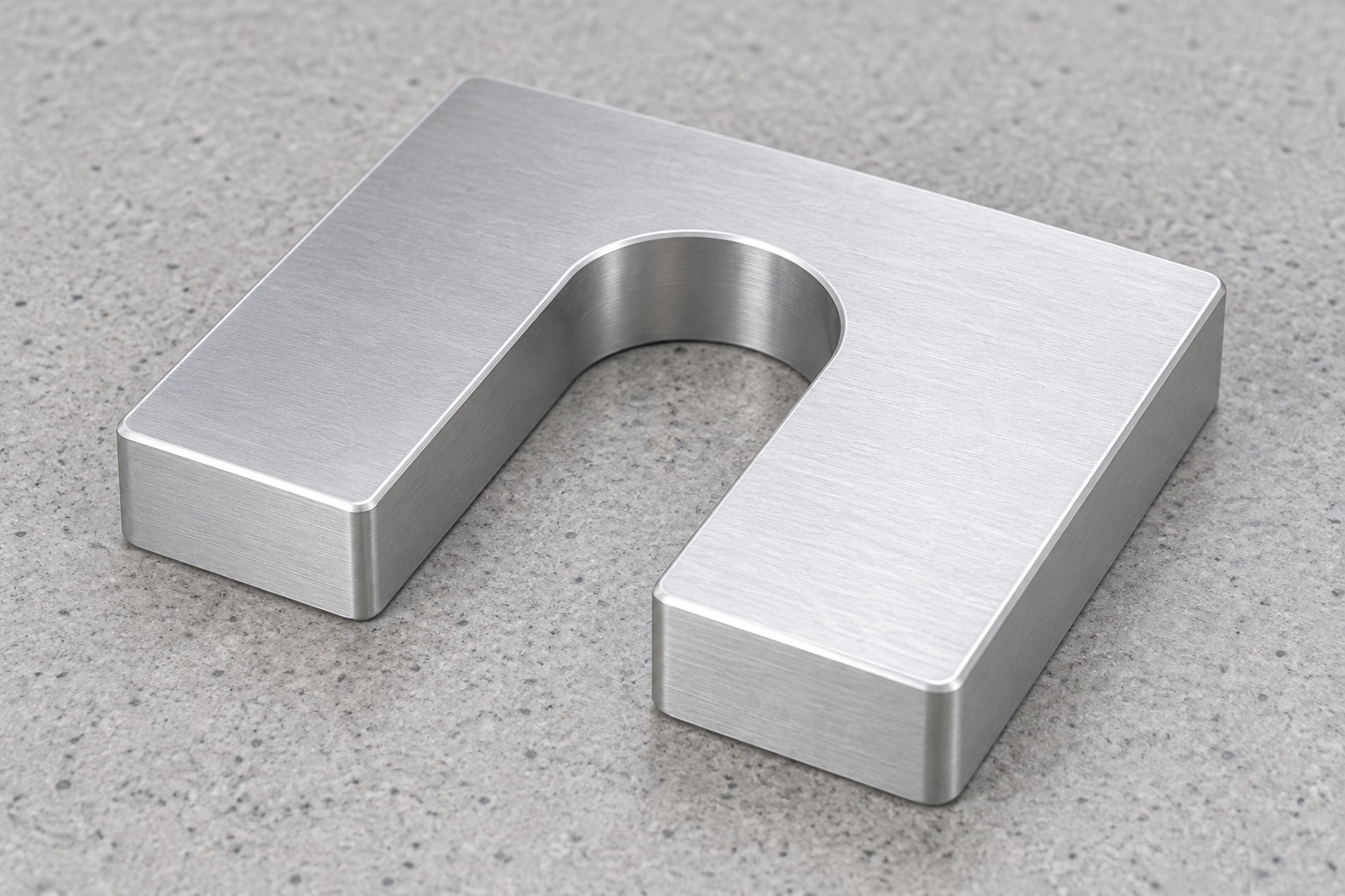
Define the spacer's limited mechanical role
A medical laboratory service module may use an open-sided spacer plate between two approved mounting surfaces. The illustrative component is a single aluminum plate with a rectangular outside profile and one deep U-shaped slot opening through its front edge. It has parallel slot walls, a rounded root, broad opposing faces and no holes or threads. Its purpose is a specified mechanical separation and access arrangement, not an independent locking device. The illustrations are concepts, not approved dimensions, a delivered assembly or measured evidence of module retention, load capacity or validated medical equipment safety.

Identify the complete mounting stack
Obtain the controlled plate drawing and model, both mating surfaces, the mounting stem or fastener, and the actual installation revision. Specify which areas contact the spacer and how the assembly retains it. An open slot permits a defined installation path, but does not prove that the plate cannot move during service. Do not assume a washer, nut, latch or retaining feature from an illustration. The equipment team should define the actual stack and installation method. A nominal gap measurement alone cannot identify every contact, edge clearance and retention requirement that the supplier needs before manufacture.
Make the side-entry path explicit
Define slot width, root profile, opening direction and position relative to the accepted references. Review the entire path around the identified stem, surrounding hardware and available service space. A component fitting at its final position may still be impossible to insert along the intended path. The supplier should not open the slot, shorten an arm or change the root to fit an unidentified sample. Any geometry adjustment requires authorization. A proposed opening does not establish a safe maintenance procedure or permit removal under load; such application decisions belong to the responsible equipment team and actual service documentation.
Control useful faces and final separation
Specify finished thickness, useful contact areas and their required relationships. Distinguish permitted chamfers and noncontact regions from the faces that establish the actual separation. A stock thickness or one micrometer reading is not a complete definition of the installed stack. Agree the measurement condition, support and relevant final process. Do not use mounting force to conceal a bowed plate and call that dimensional acceptance. If the assembly needs a defined preload, stiffness or resistance to movement, those are separate requirements for the actual complete stack, not properties established by a smooth aluminum spacer photograph.
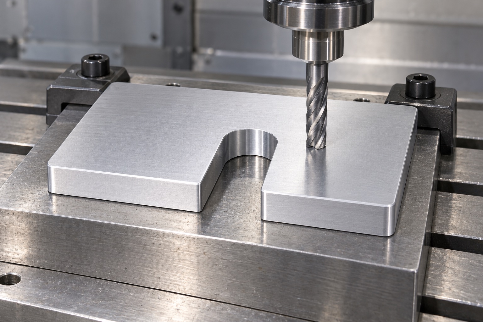
Review arm width and slot-root transitions
The remaining side sections and rear bridge should follow released dimensions and edge requirements. Clarify whether any outer edges locate the component or simply provide clearance. A rounded slot root is not permission to choose any convenient cutter radius. Model and drawing conflicts should be resolved before finishing the profile. The supplier must preserve useful contact near the opening rather than polish it away to make one trial slide easily. No numerical load or universal minimum wall is prescribed here; the equipment designer must define the real component geometry and independently qualify relevant application behavior.
Specify the aluminum and finished condition
Identify the approved 6061 grade, stock condition, form, material records and purchased final treatment. A silver illustration does not select untreated, anodized or another finished state. Include checks after processes that can influence thickness, contact or slot clearance. Preserve material and revision identity through blank preparation, opening the slot and shipment. Material evidence identifies stock within its actual scope; it does not establish biological compatibility, validated cleaning, sterile delivery or equipment certification. Do not transfer a commercial shim's rating or an unrelated bracket's performance to this custom plate merely because the alloy name is similar.
Plan holding around the open section
Review support and machining sequence before removing material for the U slot. Protect useful faces and avoid relying on a fixture-distorted condition as acceptance. Remove chips from locating contacts when the component is reoriented. Carr Lane's locating and clamping principles provide general workholding background, not approval of this spacer, fixture or medical equipment installation. The actual route should preserve references between faces and profile. Intermediate measurements can support process development, but the final inspection must address the specified released condition. This article supplies no universal clamp force, machine settings or unsupported promise of achieved flatness.
Finish edges without changing the contact envelope
Inspect slot entries, the rounded root, arm ends and outer corners for attached material or unwanted sharp features. Apply approved edge breaks without reducing useful contact or enlarging the side-entry path beyond the drawing. Hand finishing that changes the profile requires controlled review rather than disappearing as cosmetic work. Cleaning should match the purchased scope and preserve the accepted condition. A bright surface does not demonstrate low particles, antimicrobial action or compatibility with every maintenance chemical. Where residues or surface properties matter, specify appropriate methods and evidence for the actual material, finish and equipment environment.
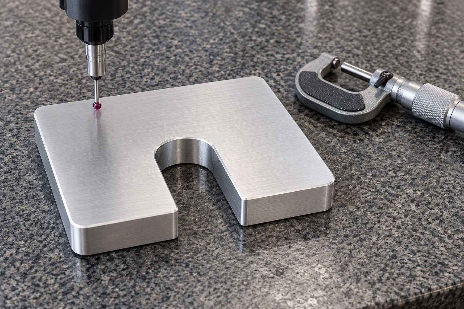
Connect each requirement to an inspection method
The plan should cover thickness, useful faces, slot width and root, profile position and required geometric relationships. Identify references, support, final treatment and measurement access. A caliper checking outside size cannot independently verify all contacts and the opening. If a probe cannot reach a functional region, agree a suitable method before acceptance. Record numbered characteristics, drawing revision, material lot and actual observations on a real report. A CMM or micrometer illustration shows possible tools, not a measured result or achieved tolerance. Distinguish dimensional inspection from optional observations using an identified mounting stem and module.
Keep fit observations separate from retention tests
An optional assembly observation may examine entry path, seating, stem clearance and service access with identified spacer, module, support and fastener revisions. Record the installation method and approved retention components. Favorable hand insertion does not establish load capacity, vibration resistance, preload stability or safe removal during operation. Those require separately defined evaluation of the actual assembly and intended service conditions. Trial plates should remain distinct from accepted production. Unexpected interference should trigger review before altering the slot, mating surface or hardware simply to obtain an easy demonstration or using the trial as a general production gauge.
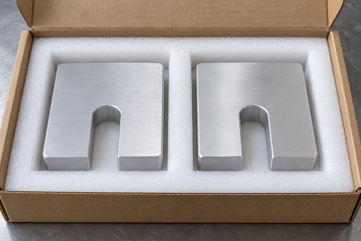
Protect contact faces and open arms in transit
Separate finished plates in supports that protect the broad contacts and slot edges without bending the open arms. Loose fasteners must not strike accepted surfaces. Packaging dimensions and restraint should preserve the inspected condition, not squeeze the U-shaped part into a distorted position. Mechanical transit protection does not imply sterile delivery. Keep lot, revision, final treatment and acceptance status with the shipment. Receiving staff should distinguish similar outlines with different thickness, root radii or slot widths before installation and before the equipment team's independent retention, maintenance or environmental evaluation of the actual medical laboratory module.
Submit a stack-specific manufacturing inquiry
Provide the controlled drawing and model, both mating surfaces, actual stem and retention hardware, insertion path, useful contact areas, finished thickness, material, final processing and inspection deliverables. Identify optional fitting separately from load, retention and service qualification. Review changed supports, fasteners, module geometry or treatments before repeating manufacture. Incorporate authorized prototype changes into revised documents rather than keeping a hand-filed plate as the next production reference. This creates a traceable CNC supply scope without inventing measured performance or confusing a conforming open-sided spacer with an independently qualified medical equipment locking or support system.
Manufacturer background reference: www.carrlane.com.
FAQ
Does the open slot lock the spacer in place?
No independent locking function is established. The actual assembly must define how the spacer is retained. Slot geometry and successful insertion do not prove resistance to movement, vibration or load. Those requirements need separate application definition and verification.
Does final fit prove the installation path is clear?
No. Review the full side-entry path around the identified stem and surrounding hardware. A plate that fits its final location may not be insertable as intended. Do not change the slot or arm geometry without authorized design review.
Can fastening force correct a bowed plate?
It should not replace agreed final-state contact and thickness requirements. Define references and measurement support, then review discrepancies. A forced flat installation may conceal a component or interface issue rather than demonstrate conformity of the delivered spacer.
Is stock thickness a finished dimension?
Not automatically. The approved drawing and purchased processes define final thickness and useful face relationships. Material stock size and a single favorable reading do not establish all required geometry or the complete installed separation.
Does the illustration specify a load rating?
No. It is a mechanical concept without measured load, retention or stiffness results. The responsible equipment team must define and qualify relevant behavior using the actual spacer, mounting stack, retention method and service conditions.
What should repeat-order review cover?
Review module and support interfaces, stem, retention hardware, slot path, thickness, useful contacts, material and final treatment. Approved changes belong in controlled documents, not a manually adjusted plate or performance assumptions transferred from another installation.

tanghangyun@oemach.com