
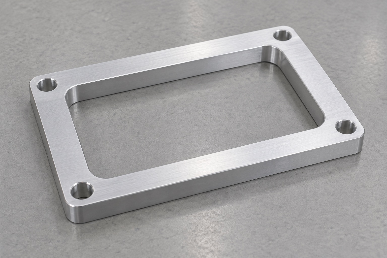
Start with the detector mounting interface
A detector module in a medical laboratory instrument may need a separate machined adapter between its housing and the equipment structure. This article considers a flat aluminum rectangular frame with one rounded rectangular through opening and four plain mounting holes. The useful mechanical interfaces are the mounting lands, opening boundary, hole pattern and finished thickness. The illustrations are concepts, not approved dimensions or evidence of a delivered detector assembly. A frame that fits four screws does not establish optical alignment, diagnostic accuracy, electrical safety or electromagnetic shielding of the complete instrument.

Release both sides of the contact stack
Obtain the controlled frame model and drawing, detector housing details, instrument support and actual fasteners. Identify which face contacts each mating component, which areas must remain open and whether washers or separate locating features are present. Four clearance holes should not silently become precision locating bores. If the detector is adjusted elsewhere, record that arrangement instead of asking the supplier to infer alignment from a photograph. Resolve conflicting interfaces before machining. A correct outside length does not show that the frame seats correctly between the actual detector housing and equipment mounting surface.
Specify the usable opening rather than a silhouette
Define the opening profile, corner radii and its position relative to the accepted references. Clarify the clearance envelope for the actual detector body, connectors, cable exit and any separate optical path. An opening that passes one housing sample may still interfere with another approved condition if the drawing is incomplete. Do not enlarge a corner or thin a frame wall informally to remove a contact. The equipment designer must authorize changes to material around the opening. The frame concept itself is not an aperture specification or a claim about stray light, imaging quality or measurement performance.
Control mounting lands and finished thickness
Define useful face areas, thickness and the relationships required between the two contact sides. Distinguish functional seating surfaces from permitted chamfers and processing regions. A thin frame can appear acceptable while restrained against a fixture, so the agreed final inspection condition matters. Do not rely exclusively on screws pulling a bowed frame against the detector housing. Clarify whether the drawing controls a local contact area or the whole face, and identify how that requirement will be measured. Adding a gasket or spacer to conceal a seating discrepancy requires an approved assembly decision, not a machining workaround.
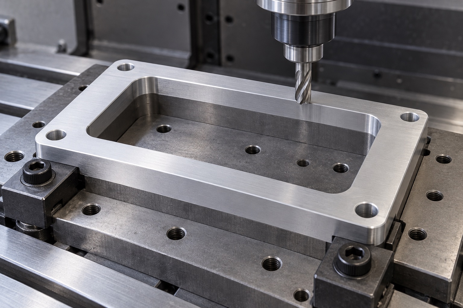
Treat hole identity and position separately
For every mounting feature, specify hole type, size, position and any edge treatment. The illustrated four holes are plain through holes, without threads or counterbores. A supplier should not add a recess simply because a convenient screw head stands proud. The assembly documents should identify screw access and the actual grip length. A pin entering one hole does not establish the complete pattern, opening location or seating relationship. If an accepted design uses separate dowels, those features require their own references and inspection scope rather than an assumption that all holes locate the detector equally.
Keep aluminum and final treatment traceable
Specify the approved 6061 stock condition, form and material evidence together with the purchased surface process. A silver illustration does not choose between untreated, anodized or otherwise finished supply. Any final process affecting hole clearance, contact dimensions or assembly interfaces should be included in the acceptance plan. Maintain material and revision identity through roughing, finishing and shipment. Material certification identifies the supplied stock within its scope; it does not establish detector calibration, electromagnetic performance, biological compatibility or validated cleaning. Do not transfer properties from an unrelated catalog enclosure merely because both parts are aluminum frames.
Support the frame without accepting fixture distortion
Plan holding contacts and the sequence of outside, opening and mounting-feature operations before production. Carr Lane's locating and clamping guidance is general background for controlling a workpiece, not approval of a particular frame fixture or detector mounting design. Protect useful lands from clamp damage and avoid relying on a heavily restrained condition as final acceptance. Remove chips from references when the part is reoriented. Intermediate checks can inform the route, but the released component must meet its agreed finished-state requirements after relevant operations. No universal clamp force or cutting settings are prescribed by this illustrative article.
Finish internal corners without changing clearance
Inspect opening edges, corner transitions, mounting-hole entries and outer boundaries for attached material or unwanted sharp features. Apply the released edge requirements while preserving useful lands, wall thickness and the defined clearance envelope. Polishing until an unidentified detector housing drops through is not a substitute for an authorized geometry change. Keep permitted cosmetic conditions separate from dimensional requirements. Cleaning and final processing should follow the purchased scope. A bright or smooth frame does not independently prove low particles, antimicrobial behavior, sterile supply or compatibility with every maintenance chemical used around a medical laboratory instrument.
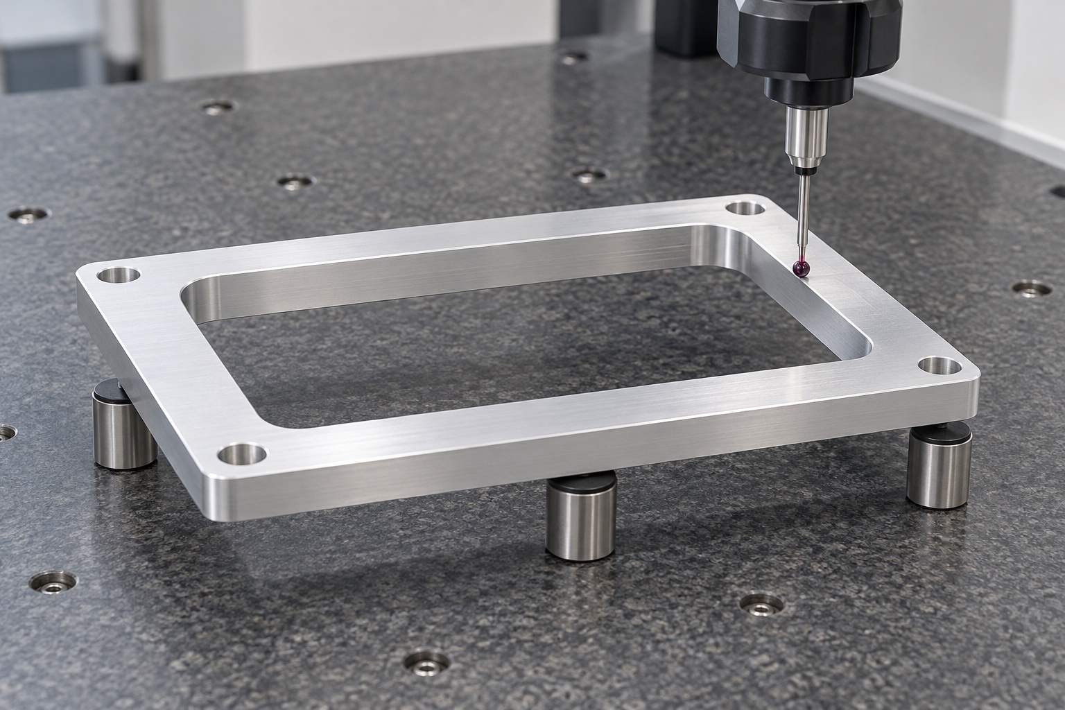
Map each characteristic to an inspection method
The inspection plan should cover opening profile and position, mounting pattern, useful faces, thickness and required geometric relationships. Identify support, final treatment, reference establishment and suitable contact access. A caliper can address selected sizes, but outside dimensions alone cannot verify every relationship. Where a probe cannot reach a corner or useful land directly, agree an appropriate method before accepting the work. Retain numbered characteristics, drawing revision and actual observations in the report. The illustration of a CMM is a possible setup, not a measured result, achieved tolerance or proof of a qualified detector assembly.
Separate mechanical fitting from detector validation
An optional assembly observation can examine seating, screw access, opening clearance and cable passage with identified frame, detector housing, support and fastener revisions. Record the installation method and any approved washers or locating elements. A favorable fit does not demonstrate optical alignment, calibration stability, electromagnetic shielding, vibration life or medical equipment safety. Those claims need separately defined evaluation of the actual complete system. Keep trial pieces distinct from accepted production. Unexpected interference should enter controlled review before adjusting the frame, detector or support merely to obtain a successful assembly demonstration.
Protect open frames during handling and shipment
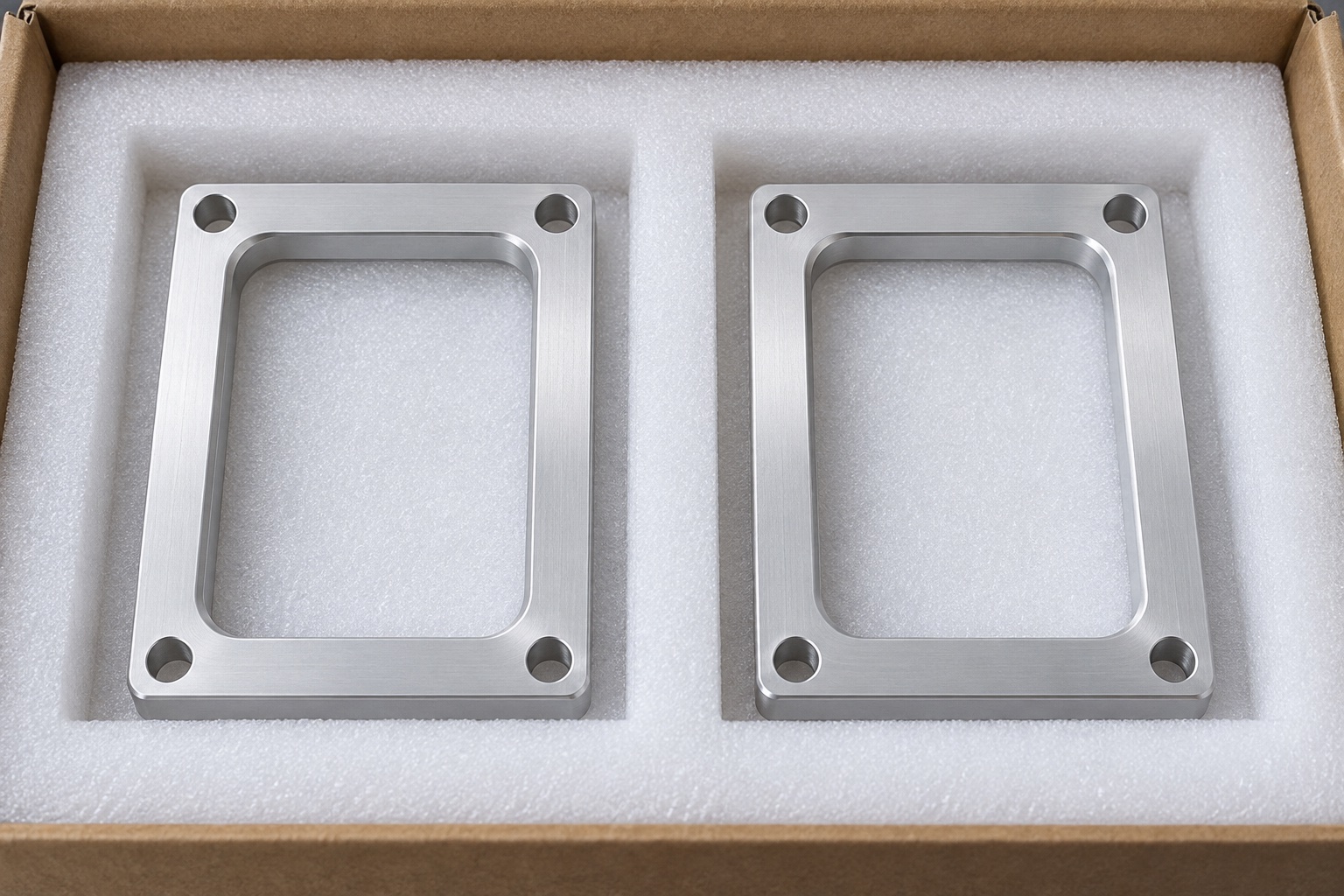
Use separated supports that protect the contact lands and opening edges without bending the frame. Do not stack loose fasteners against accepted surfaces or squeeze a thin ring into an undersized pocket. Packaging should preserve the inspected condition and the identity of the material lot, revision and final treatment. Mechanical protection is not sterile delivery. Receiving staff should distinguish frames with similar outside dimensions but different opening radii, hole positions or thickness. Preserve the link between inspection records and the delivered component before the equipment team begins assembly and any independent detector setup or application-specific qualification.
Make the inquiry specific to the real interface
Provide the controlled drawing and model, both mating components, useful contact areas, opening envelope, fastening and locating arrangement, material, final process and inspection deliverables. Identify optional fit observations separately from optical, electrical and complete-equipment qualification. Review changed detector housings, connectors, support plates or surface treatments before repeating manufacture. Approved prototype adjustments should enter revised documents rather than leave a manually filed frame as the next production reference. This creates a clear CNC supply scope without inventing measured performance or confusing a conforming mechanical adapter with a qualified medical detector subsystem.
Manufacturer background reference: www.carrlane.com.
FAQ
Do the four holes locate the detector precisely?
Not necessarily. The illustrated holes are plain mounting clearances. Actual location depends on the released assembly and any separate locating or adjustment features. The supplier should not infer precision registration from screw count or a familiar mounting pattern.
Does the opening define optical performance?
No. It is a specified mechanical clearance in this concept. Optical paths, alignment, stray-light control and detector calibration require separate application definitions and evidence. A housing fitting through the frame is not a detector performance test.
Can screws flatten a bowed frame for acceptance?
That should not replace the agreed finished-state seating requirements. Establish the actual references and measurement condition, then review discrepancies through controlled documents. A forced installation may conceal an interface issue rather than demonstrate a conforming free component.
Can the supplier add counterbores for convenient screws?
Only through an authorized design change. Plain holes, counterbores and threads have different geometry and installation consequences. Actual fasteners and access must be specified instead of changing the frame to fit unidentified hardware.
Does an aluminum frame provide proven shielding?
No shielding result is established here. Material identity and shape alone do not qualify electrical continuity or electromagnetic performance of the complete installation. Define any relevant requirements, finished contacts and testing separately for the actual equipment.
What should a repeat-order review include?
Review both mating parts, opening clearance, useful lands, thickness, hole pattern, fasteners, locating features, material and final treatment. Preserve approved revisions and measured acceptance records rather than copy a hand-adjusted frame or another detector assembly's performance claims.

tanghangyun@oemach.com