
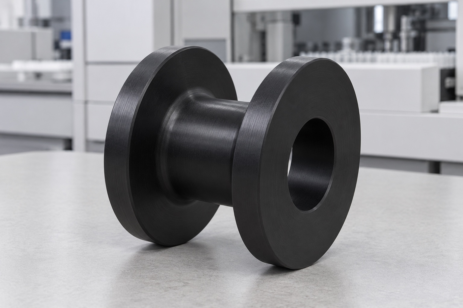
Define a stationary cable contact component
A medical equipment service cable may need a defined stationary guide within an approved routing arrangement. A turned spool can provide a cylindrical contact region and side flanges, but it is not automatically a rotating reel, strain relief or dynamic cable carrier. This article concerns equipment-side CNC manufacture of a proposed black POM guide. Illustrations show a plain coaxial through-bore, smaller cylindrical waist and two equal end flanges without a cable or bearing. They are concepts, not a validated route, manufactured sample or measured medical equipment performance record.

Use the actual cable manufacturer's requirements
Identify the exact cable, connector, jacket and installation revision before defining its contact geometry. igus distinguishes fixed, flexible and continuous-motion bend requirements in its cable guidance; that background does not approve this proposed spool or supply a universal radius for another cable. The responsible equipment team must obtain the applicable cable requirements and release the route. Avoid selecting geometry from cable diameter alone. A fixed guide concept should not be introduced into a moving cable path without separate review of motion, contact, retention and the complete medical equipment service arrangement.
Distinguish waist radius from cable routing radius
The spool drawing should identify the relevant waist surface, useful contact region and relationship to the mounting bore. The cable requirement may use its own defined reference for bend radius, so the spool's outside diameter should not be substituted without checking that definition. Define how the actual cable approaches and leaves the contact region. A visually generous curve does not establish conformity. Resolve any reference ambiguity before turning, rather than enlarge or reduce the waist to fit an unidentified cable and assume that the original routing requirements remain satisfied in the enclosure.
Make flange clearance and transitions explicit
Specify the separation, useful inner faces, edge treatment and root transitions of the two flanges. The route should distinguish intended guidance from an unintended pinch or rubbing contact. Connector installation and removal may need more room than the cable's nominal outside dimension. The supplier should not thin a flange, widen the waist region or add a slot informally to improve a demonstration. Tool access and permitted corner radii need review before production. The released drawing and assembly, not the familiar bobbin appearance, must define which surfaces may contact the cable jacket.
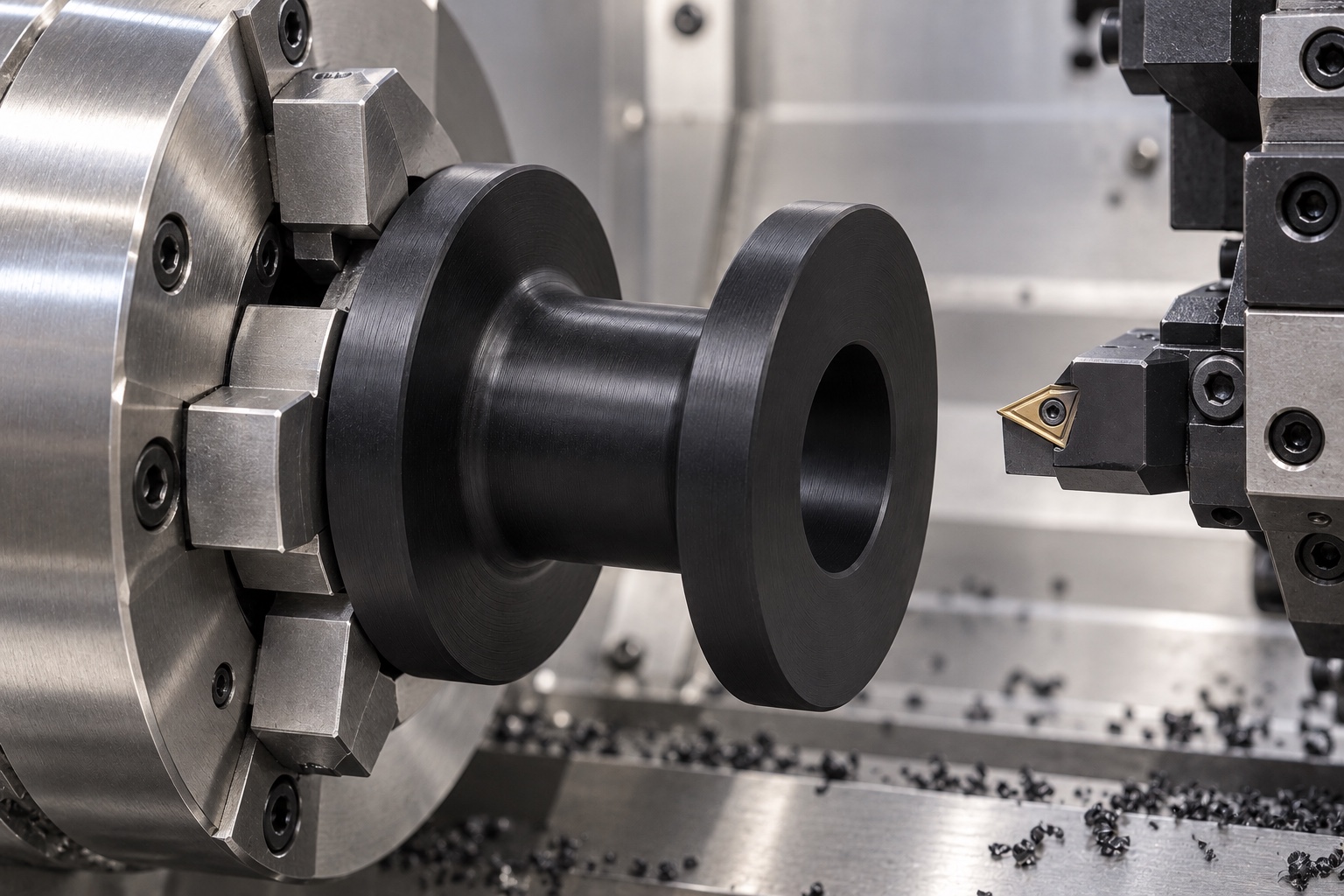
Define mounting without implying a bearing
Specify the bore, seating faces, spacers, retention and installation condition for the actual stationary arrangement. A plain central hole does not define a rotating support or establish that the guide can be clamped anywhere without changing the waist or flanges. The equipment designer should identify useful mounting contacts and any prohibited compression. Do not add a bearing, sleeve or improvised washer to make a trial rotate or feel secure. Any change in support or retention must be authorized and documented separately from the machined spool's dimensional acceptance.
Select the exact polymer and final condition
Specify the approved POM grade, stock form, material evidence and any relevant final processing. Black color does not establish equivalence among polymers or modified grades, electrical insulation, flame behavior or compatibility with a cable jacket. Preserve stock lot identity through turning and shipment. Cleaning and packaging should follow the purchased scope without suggesting medical certification or sterile supply. The actual equipment team must separately evaluate any chemical exposure, particle, electrical or service-life requirements. Generic material identity and a smooth appearance cannot independently qualify a finished guide for every medical instrument cable arrangement.
Plan the waist and flange turning sequence
Review gripping contacts, stock allowance, roughing, finishing and setup transfer so both flanges, waist and bore remain related after unclamping. Thin flanges or excessive restraint can make the observed condition differ from the released part. Clear chips from holding and locating surfaces before reorientation. No universal cutting values are prescribed here. The supplier should preserve accessible inspection regions and avoid accepting the guide only under distortion from the fixture. Intermediate observations can support route development, but the final report concerns the agreed conditioned and finished component rather than convenient machine coordinates.
Finish jacket-contact regions deliberately
Inspect waist surfaces, flange roots, edges and bore entries for attached material or unwanted sharp features. Apply the approved edge requirements without broadly polishing the waist to a different contact size or changing the inner flange space. Cleaning must preserve accepted surfaces and follow the agreed polymer-compatible scope. Smooth-looking black plastic does not demonstrate low jacket abrasion, quantified particles or validated decontamination. Any authorized surface change should remain traceable. A hand-finished sample must not become an undocumented production baseline that changes cable contact while the equipment routing drawing remains unchanged.
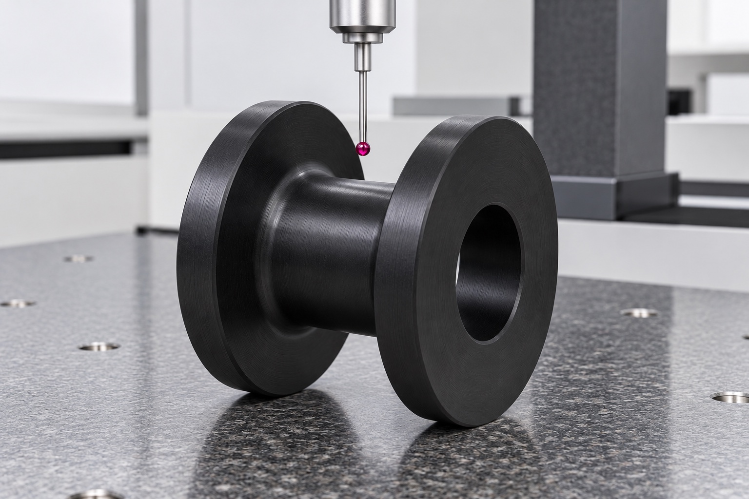
Inspect the complete guide geometry
Map the specified waist, flange separation, root transitions, bore, faces and reference relationships to accessible inspection methods. Define conditioning, support and measurement contact for the polymer part. Measuring flange diameter and checking one bore entry alone may not address the useful contact region or inner spacing. Resolve inaccessible or ambiguous characteristics before production rather than substitute an attractive cable-fit photograph. An identified cable can support a limited assembly observation but is not automatically a dimensional gauge. Keep reports linked to the actual component revision, material lot and agreed final measurement state.
Separate route observations from cable qualification
An optional trial can examine installation, connector passage, cable approach and exit, intended contact and service access using identified components. Record the guide mounting and the cable manufacturer's applicable bend requirement. A favorable static fit does not establish jacket life, conductor integrity, electrical performance, signal quality, strain relief or suitability for repeated motion. Those need separate evaluations of the complete route under actual conditions. Trial guides should remain distinguishable from accepted production. Unexpected contact requires controlled review before trimming a flange or substituting another cable to complete the demonstration.
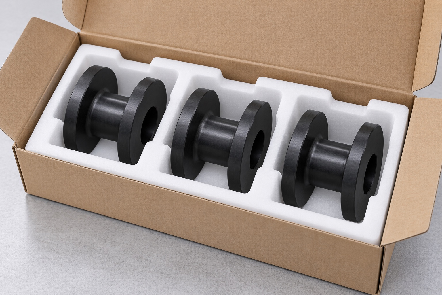
Protect contact surfaces during shipment
Separate guides so hard hardware cannot strike the waist, flange roots or bore entries. Support the component without squeezing the flange faces or embedding protective material in the cable-contact region. Preserve grade, lot, revision, conditioning and inspection status with the shipment. Protective packaging is not sterile delivery or quantified cleanliness. Receiving staff should distinguish waist, bore and spacing variants, prototypes and accepted production. Maintain component identity before the equipment team performs its approved routing, assembly and independent electrical, abrasion, maintenance or cleaning evaluations for the actual medical instrument installation.
Build a cable-specific manufacturing package
Provide the released model and drawing, exact cable and connector information, applicable radius definition, intended contact regions, mounting and retention, service envelope, polymer, final condition and inspection deliverables. Separate optional routing observations from electrical, abrasion and motion-life qualification. Review changed cables, jackets, connectors, mounting hardware or service conditions before repeating manufacture. Incorporate approved prototype modifications into controlled documents. This defines a traceable CNC scope without turning a simple bobbin shape into a universal cable guide or treating a conforming POM part as proof of validated medical equipment cable performance.
Manufacturer background reference: toolbox.igus.com.
FAQ
Does this guide act as a rotating cable reel?
Not in the proposed scope. It is a stationary contact guide in an approved equipment-side route. A rotating bearing arrangement, dynamic cable path or strain-relief function would need its own controlled design and evaluation, not an assumption based on a central hole or bobbin shape.
Is the waist radius the same as the cable bend radius?
Not automatically. The applicable cable requirement defines its own reference and installation conditions. Review that definition and the cable's actual approach and exit before translating it into guide geometry. A spool outside diameter alone cannot establish a compliant cable route.
Can a flange be trimmed to pass a connector?
Only through an authorized design decision when the controlled geometry changes. Record the actual cable, connector, guide and mounting configuration. An improvised slot or thinner flange should not become an undocumented reference or hide a routing issue in later production.
Does black POM establish electrical insulation?
No finished-component electrical claim is established by color or generic polymer identity. Specify the exact grade and evaluate any required electrical, jacket-compatibility, flame or service property for the actual guide, cable and complete medical equipment arrangement.
Does a static fit trial prove cable life?
No. It can support defined installation and contact observations with identified components. Jacket abrasion, conductor integrity, signal performance, strain relief and repeated-motion suitability require separate evaluation under actual service conditions rather than a favorable stationary demonstration.
What changes require review on another order?
Review cable and jacket, connector, applicable radius definition, waist, flange spacing, mounting, polymer and service exposure. Preserve authorized revisions instead of copying a hand-trimmed spool or transferring qualification assumptions from another medical equipment cable route.

tanghangyun@oemach.com