
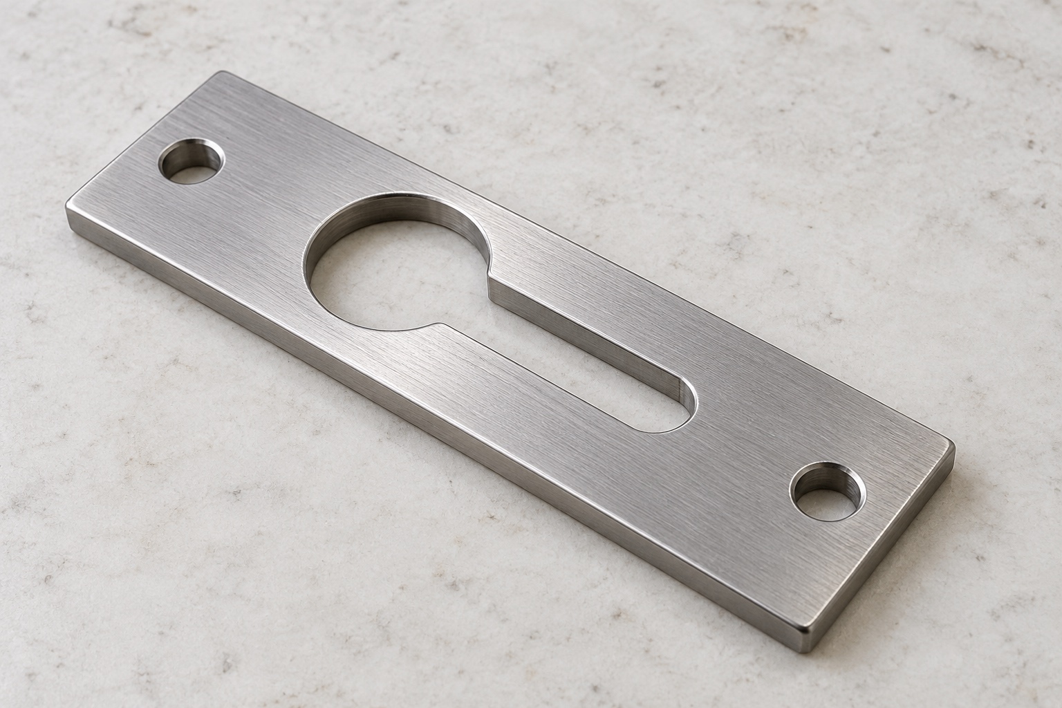
A shaped opening is not a complete locking system
A service cover in medical equipment may use a shaped retaining plate as one part of an approved attachment arrangement. A keyhole opening combines a larger entry region with a narrower sliding neck, allowing defined hardware to enter and move into its intended contact position. The complete design must define retention and release. This article addresses CNC manufacture and dimensional inspection, not a universal cover-locking solution. Illustrations show a flat proposed plate with one through keyhole opening and two mounting holes, not measured production, a tested latch or validated equipment safety.

Identify the mating hardware and cover
Obtain the approved hardware identity, head and shank geometry, cover thickness, supporting structure and installation sequence. The large entry region and narrow neck must be reviewed with the actual mating arrangement rather than a similar screw. Clarify whether the plate is fixed to the cover or equipment frame and identify relevant contacts. A generic keyhole sketch is not an assembly definition. Resolve missing hardware or orientation information before manufacture so the CNC supplier does not invent clearances, release travel or a locking method to suit an unidentified prototype and medical equipment installation.
Define the entry region and transition
The larger opening must follow the approved entry geometry, location and edge requirements. Review its transition into the sliding neck, including any permitted internal radius. An entry diameter alone does not define the complete insertion path. The responsible designer should identify which contacts are functional and which areas require clearance. Do not enlarge the opening until an unrelated screw passes through. Changes to the entry or transition can affect the remaining plate and actual installed behavior, so they require a documented decision rather than an informal finishing adjustment during assembly.
Control the neck width and useful travel
Specify the narrow region's width, end shape, length and relationship to the mounting references. Distinguish the useful sliding path from a relieved or rounded region that is not intended to carry contact. Review actual hardware and cover movement together. The machining supplier should not extend the slot or reduce the shank to make the cover slide. A loose movement demonstration does not establish correct retention. Any approved change must enter controlled geometry and inspection documents instead of relying on a particular fastener sample or an operator's interpretation of the keyhole shape.
Relate plate thickness to contact stack
The actual under-head space, plate thickness, cover and neighboring components determine the installed contact arrangement. Define the relevant seating faces and final surface condition rather than treating the outside profile alone as acceptance. The supplier should not add washers or remove material until a cover appears tight. Such changes may conceal an incorrect hardware variant or incomplete seating. No universal tightening torque, preload or retention capacity is specified here. Those belong to the approved assembly and must be evaluated independently for the actual medical equipment and service conditions.
Keep retention and deliberate release explicit
A keyhole shape by itself should not be described as a positive lock, interlock or vibration-qualified retainer. The responsible equipment program must define how the cover is retained in normal service and how authorized release occurs. Review any additional fastener, latch or other controlled feature without assuming it from the illustration. The cited Dranetz instructions provide background on an unrelated instrument's keyhole mounting kit; they do not approve this proposed medical cover plate, transfer hardware dimensions or establish any comparable installation, retention, environmental or safety performance for the custom component.
Specify stainless condition and final process
Identify the approved stainless grade, stock form, condition and required material evidence. A proposed 316L plate is not automatically equivalent to a catalog latch or rated lifting fitting. Preserve lot traceability through manufacture and shipment. Any passivation, coating or other final process should have agreed coverage and relevant final-state inspection. Material identity and bright appearance do not establish measured corrosion resistance, sterile status or adequate retention under every condition. Evaluate actual material, surface and assembly requirements through the responsible design program before approving substitutions or repeat production.
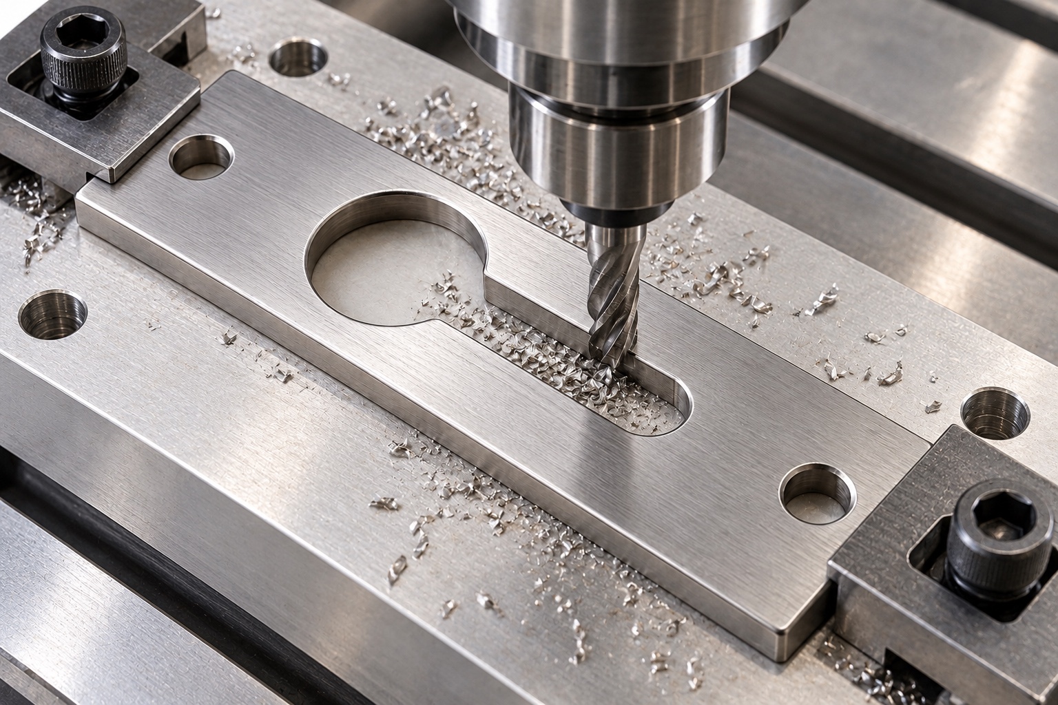
Machine the opening with stable support
Review blank preparation, roughing, finishing and fixture support around the keyhole opening and mounting regions. Material removal can change a thin plate's behavior after it is released, so avoid accepting geometry only while heavily restrained. Keep chips away from fixture contacts during setup transfers. Tool access and approved internal transitions should be considered before production. No universal toolpath is prescribed. Intermediate checks may support the route, but final acceptance should address the agreed finished component state, including its useful contacts and the relationship between entry, neck and mounting pattern.
Finish edges without erasing useful contact
Inspect entry edges, neck boundaries, mounting-hole exits and outside corners for attached material or unwanted sharp features. Apply the approved edge requirements without turning the neck into a wider path or rounding away useful contact under the hardware head. Do not polish until one sample slides easily. Cleaning and any later treatment follow the purchased scope and should preserve the inspected geometry. A smooth-looking plate is not evidence of a tested release force, wear life, quantified cleanliness or qualified retention function in the medical equipment cover assembly and its actual operating environment.
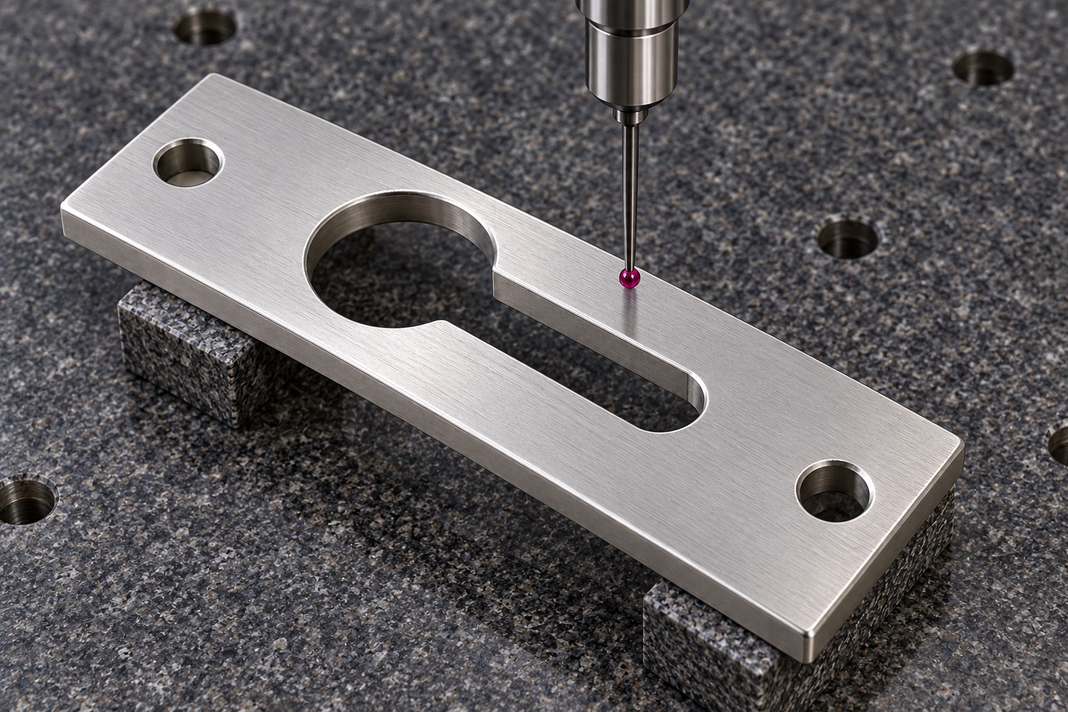
Inspect the whole insertion and sliding geometry
Map entry size, transition, neck width, useful travel, thickness and mounting relationships to suitable accessible methods. Identify final treatment and support conditions. A single screw-fit observation or outside-size report does not verify all controlled characteristics. If a requirement cannot be checked reliably, clarify it before manufacture rather than reporting a convenient substitute. An optional assembly demonstration should identify hardware and cover revisions and remain separate from dimensional acceptance. Preserve traceability so an apparently successful loose fit does not become the universal gauge for another keyhole plate or installed equipment configuration.
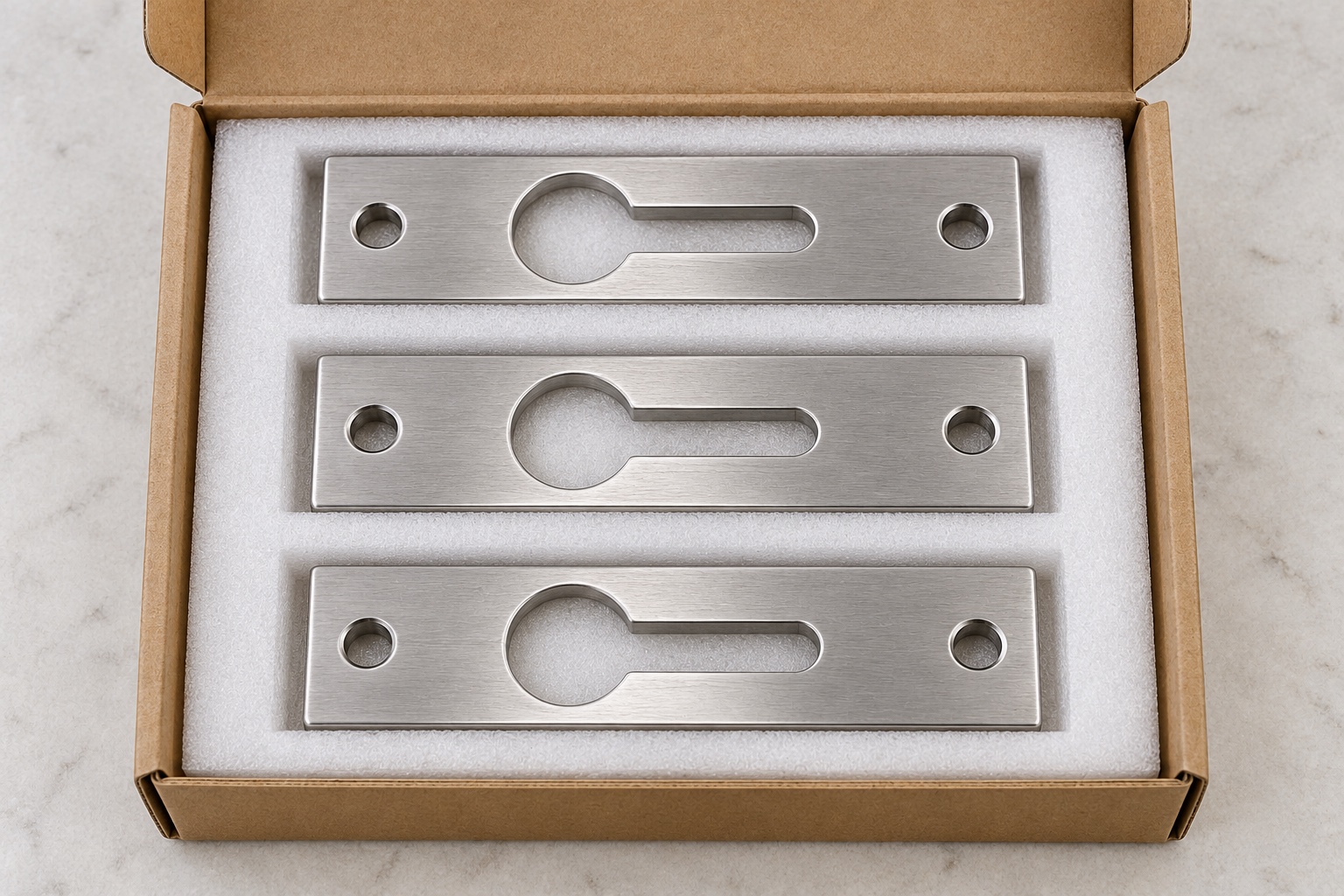
Protect slot boundaries and identify variants
Separate finished plates so neighboring studs and edges cannot strike the neck or entry transition. Support thin regions without distorting them through packaging pressure. Protective materials and cleaning status should follow the agreed scope without implying sterile delivery. Keep material, lot, thickness variant, revision and acceptance status identifiable. Receiving personnel should distinguish released plates from prototypes and modified trial pieces before assembly. Visually similar keyhole parts with different necks, entry sizes or thicknesses should not be substituted merely because an available screw can enter and slide through them by hand.
Keep the inquiry tied to the actual assembly
Provide controlled geometry, exact hardware, cover and frame contacts, insertion and release sequence, material, final treatment and inspection deliverables. Identify optional mechanical trials separately from retention, vibration, access-control and equipment safety evaluations. Review changed head geometry, thickness stack, additional latch or release travel before relying on earlier observations. Incorporate authorized changes into revised documents rather than copying a hand-adjusted plate. This defines a traceable CNC scope without claiming that a shaped opening or successful cover assembly proves a rated locking function or validated safety outcome for unspecified medical equipment.
Manufacturer background reference: www.dranetz.com.
FAQ
Is a keyhole plate automatically a positive lock?
No. Its geometry alone does not establish locking, interlocking or vibration-qualified retention. The approved complete assembly must define retention, deliberate release and any additional controlled features, with separate evidence for the actual equipment and service conditions.
Does any screw that passes through establish compatibility?
No. Head and shank geometry, under-head space, plate thickness, sliding neck and cover contacts all matter. Use the exact approved hardware; a convenient screw-fit observation should not authorize dimensional changes or establish complete retention performance.
May the narrow slot be lengthened for easier release?
Only after authorization when controlled geometry changes. Record the actual hardware, cover revision and interference first. Useful travel and retention belong to the complete assembly, not an informal adjustment made to obtain an easy prototype demonstration.
Does 316L establish a catalog load rating?
No. Material identity does not transfer another product's capacity or qualification. The custom geometry, condition, final process and installed assembly need their own approved requirements and evaluation; this article supplies no retention, vibration or lifting rating.
What should inspection cover beyond outside size?
It should address the agreed entry geometry, transition, neck width, useful travel, thickness and mounting relationships in the specified final condition. A mating screw used for a defined trial does not automatically replace all drawing-based inspection requirements.
What should be reviewed for another order?
Review exact hardware, head clearance, plate and cover thickness, neck, release travel, additional retention features, material and treatment. Preserve controlled revisions rather than copying an altered plate or transferring another equipment mounting arrangement's safety and retention claims.

tanghangyun@oemach.com