
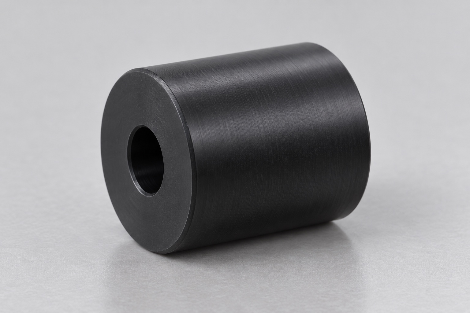
A rolling support outside the sample path
A medical laboratory instrument may use a small polymer roller to support an equipment tray during insertion or transport. The roller's bore, running surface and end faces form a mechanical interface with an axle and the tray underside. This article addresses a proposed equipment-side component, not direct patient contact, specimen contact or sterile processing. CNC inspection can verify specified geometry but cannot establish sample integrity or complete transport performance. Images illustrate a plain cylindrical roller with one central through bore, not an accepted production record or a bearing-qualified assembly.

Identify the actual tray and axle
Obtain controlled tray, axle and mounting information before defining the roller. Clarify the approved rolling contact and whether the bore runs directly on a shaft or accommodates another explicitly specified component. A plain opening in an illustration does not authorize a press fit, bearing insert or lubricant. The equipment designer should define support arrangements, retention and neighboring clearances. Resolve missing information before manufacture rather than letting the supplier infer the rolling mechanism from a similar commercial wheel, a loose shaft sample or the apparent space beneath the tray.
Relate the running diameter to the bore
When the approved design depends on the relationship between the outside running surface and bore, specify it explicitly with suitable references and inspection requirements. Do not replace that relationship with an outside diameter alone. Clarify which axial regions actually contact the tray so unused shoulders or chamfers are not measured as functional surfaces. A smooth-looking cylinder may still fail an important drawing characteristic. The appropriate tolerance belongs to the real installation and should not be copied from an unrelated roller, catalog bearing or generic precision machining capability statement.
Define axial support and end clearance
The assembly should identify the roller's useful length, end contacts and required clearance to adjacent supports. Retention features belong to the controlled assembly, not an improvised washer stack added during testing. Review actual axle shoulders, fasteners and tray envelopes together. A roller that turns freely by hand on an empty bench may behave differently when installed and constrained. Do not shorten its body or face the ends until it spins without first recording the interference and obtaining approval for any change to the controlled geometry or retention arrangement.
Select the polymer as a specific grade
Specify polymer identity, stock form and required material documentation rather than requesting any black plastic. Ensinger identifies black TECAFORM AH as POM-C supplied in machining stock shapes; this is material background, not approval of every POM roller for medical equipment. The order must identify the actual accepted grade. Assess the real operating and cleaning conditions through the responsible equipment program. Color and appearance do not establish chemical compatibility, biocompatibility, electrical behavior, wear life or suitability for direct sample contact in an unspecified instrument and laboratory process.
Consider dimensions under the agreed conditions
Define how the finished polymer component will be conditioned, supported and measured. Time after machining, temperature and restraint may matter to the agreed inspection method, so the supplier and purchaser should resolve these conditions before production. This article does not prescribe a universal compensation factor or dimensional allowance. A bore checked while the roller is compressed in a chuck may not represent its accepted state. Any expected operating change requires an application-specific review rather than assuming that a room-temperature dimension alone establishes performance throughout a medical analyzer's service conditions.
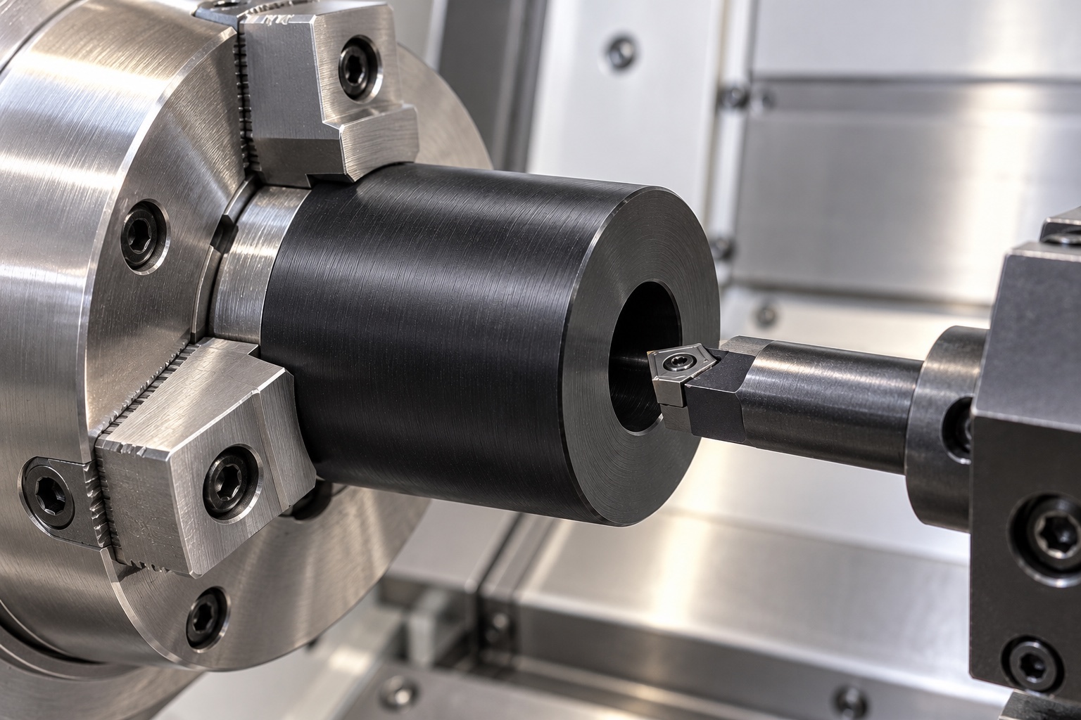
Turn without forcing the thin annular section
Plan holding contacts and stock removal so the region around the bore is not excessively compressed. Review roughing, finishing, parting and any reverse operation as a sequence. Chips should not become trapped between the component and its holding reference. A sharp tool and suitable process selection are manufacturing decisions, not universal cutting values supplied by this article. Intermediate checks can reveal route problems, but final acceptance should address the specified outside surface, bore and ends after release from the manufacturing fixture in the agreed component condition.
Finish bore exits and running edges carefully
Inspect the bore entrances, end faces and running-surface boundaries for attached material or unwanted sharp features. Apply the approved edge requirements without enlarging the bore mouth or rounding away useful rolling width. Do not polish until a trial axle slides through; resolve the actual dimensional requirement first. Cleaning follows the purchased scope and must not damage the polymer or introduce unapproved treatment. A visually tidy roller is not evidence of quantified particle generation, validated cleaning, sterile delivery or measured compatibility with laboratory reagents and decontamination practices.
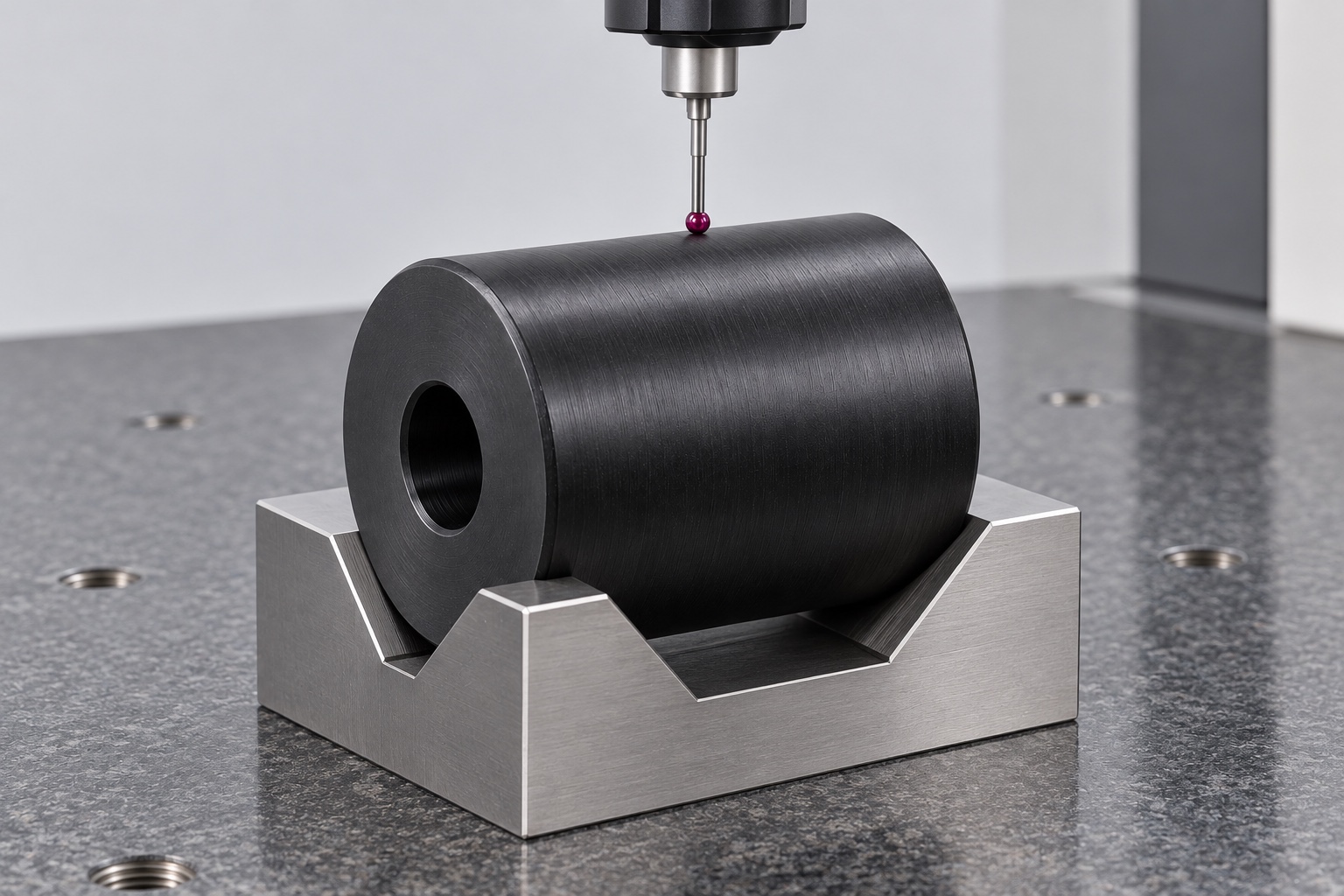
Inspect with access and contact pressure in mind
Map bore size, running diameter, useful length and specified relationships to suitable methods. Identify measurement contact pressure and support conditions where they affect interpretation. A favorable single caliper reading does not establish every geometric characteristic. If the bore or required relationship cannot be checked reliably with the available approach, agree a method before production. An axle sample can support a defined fit observation but is not automatically a gauge for all acceptance conditions. Preserve material and revision traceability with the resulting component records and any agreed deviations.
Keep rotation trials separate from transport tests
A defined trial may examine assembly, end clearance and turning behavior with identified axle and tray revisions. State whether the tray is present and what checks are actually performed. Successful hand rotation does not establish rolling resistance, load capacity, wear life, transport positioning or sample integrity. Those require separately defined evaluations of the actual assembled mechanism. Do not introduce a new lubricant or substitute axle to obtain a convenient result. Trial rollers should remain traceable so observations do not become an undocumented substitute for drawing-based acceptance or equipment validation.
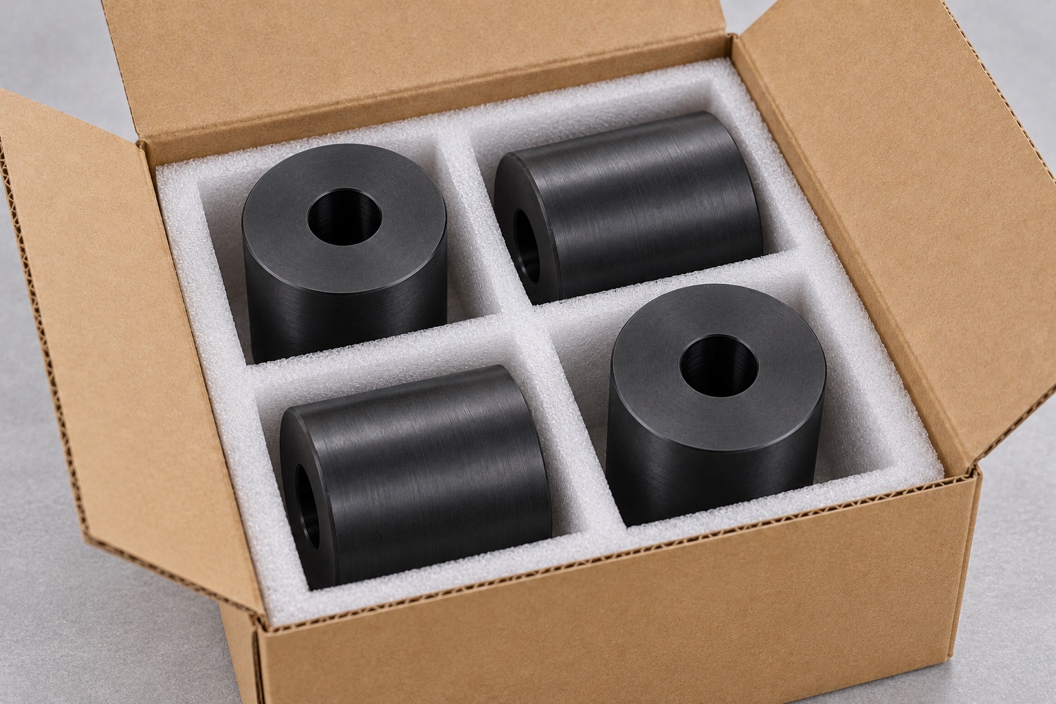
Protect the bore and running surface
Separate finished rollers so hard edges, loose axles and packing debris cannot strike the accepted surfaces. Avoid packaging pressure that distorts a polymer cylinder or forces contamination into the bore. Protective materials and cleaning status should follow the agreed supply scope without implying sterility. Keep lot, grade and revision identity with the shipment. Receiving personnel should distinguish production rollers from trial variants, different bore sizes and visually similar plastics before they enter assembly stock, preventing accidental transfer of another tray mechanism's dimensions or undocumented service assumptions.
Build a tray-specific manufacturing inquiry
Include the controlled roller model and drawing, tray contact, exact axle arrangement, end retention, material, condition and inspection deliverables. Identify optional fit work separately from transport, wear and cleaning evaluations. Review changed tray mass, contact width, axle, retention, lubricant or operating conditions before repeating earlier observations. Incorporate approved prototype changes into revised geometry rather than copying an adjusted roller. This gives the CNC supplier a defined mechanical scope without presenting polymer selection or a free-spinning sample as proof that a laboratory instrument transports medical samples accurately or safely.
Manufacturer background reference: www.ensingerplastics.com.
FAQ
Is this roller intended to contact specimens?
Not in this proposed scope. It supports an equipment tray outside the sample path. Any direct specimen, patient or sterile-process contact would need separate controlled material, cleanliness and application requirements rather than being inferred from the medical setting.
Does the central bore automatically contain a bearing?
No. The actual approved assembly must define whether the bore runs on an axle or accepts another component. A plain through hole in an illustration does not authorize a bearing, interference fit, lubricant or different retention arrangement.
Does black POM guarantee cleaning compatibility?
No. Polymer grade, actual cleaning agents, exposure and equipment requirements need application-specific assessment. Color and general material information do not establish validated cleaning, quantified wear debris, biocompatibility or sterile supply for the finished roller.
Is free hand rotation sufficient for acceptance?
No. It can support a defined mechanical observation but does not verify every drawing characteristic. It also does not establish loaded rolling resistance, wear life, positioning performance or sample integrity of the complete laboratory transport mechanism.
Why agree the measurement support state?
Holding force and measurement contact can affect a polymer component's apparent geometry. The inspection plan should identify the relevant support and conditioning requirements so acceptance does not depend on a bore measured only while compressed in a manufacturing fixture.
What changes require a new review?
Review tray contact, axle, bore, useful length, end retention, polymer grade, lubrication, cleaning and operating conditions. Preserve approved revisions rather than reusing another mechanism's observations or turning a hand-adjusted roller into an undocumented production master.

tanghangyun@oemach.com