
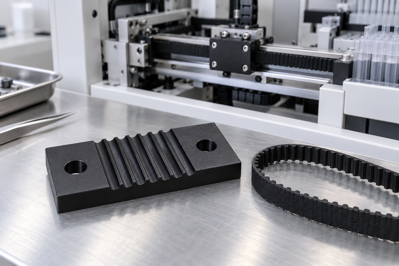
A carriage attachment rather than a pulley
A custom timing-belt clamp can connect a belt segment to a medical analyzer carriage. Its grooved contact region and mounting lands form a mechanical attachment, not a rotating pulley or a complete validated drive. The approved assembly must identify whether the clamp anchors a belt end or attaches another defined segment. This article concerns component machining and inspection. It does not prescribe a universal tooth count, tightening torque, load capacity or service life. Illustrations show representative concepts rather than measured parts or a tested analyzer mechanism.

Identify the exact belt family and profile
Obtain the approved belt manufacturer, product family, pitch, width and tooth geometry before designing the clamp surface. Gates' timing-belt theory explains pitch and geometric relationships, which is useful background but not a drawing for this custom component. Equal nominal pitch does not by itself define the entire mating profile. Do not copy an unrelated pulley shape or infer tooth geometry from an unscaled photograph. Review the actual manufacturer's information and the responsible design documents before selecting cutter access or accepting a substitute belt.
Define engaged length and contact intent
Identify the intended belt contact length, approved number of engaged features and relationship between the clamp and its mating surface. Separate intended compression from regions that must remain clear. These are assembly design requirements, not dimensions the CNC supplier should invent from a short belt sample. More grooves do not automatically demonstrate greater retention. Any change to engagement, belt direction or contact geometry requires review. An illustrated pattern indicates the manufacturing concept only and must not replace the released profile and installation requirements.
Relate the grooves to carriage mounting
Define functional base and locating references that connect the grooved region to the mounting holes and carriage interface. Hole diameter alone does not control the position or orientation of the belt contact. Review screw seating, available tool access and the mating plate together. A supplier should not introduce additional fasteners, adhesive or deeper recesses to improve a trial informally. Clarify whether holes provide clearance or location, and resolve inconsistent models and drawings before production chooses a convenient but functionally unrelated machining datum.
Specify polymer grade and service conditions
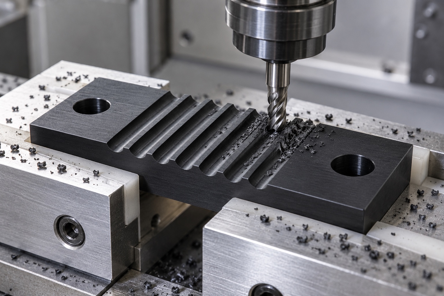
If black POM is selected, identify the exact approved grade, stock condition and required evidence. Color alone does not establish equivalence. The responsible design program should assess the intended contact, environment and loading conditions separately from machining. A material datasheet is not a finished clamp retention test, and no universal suitability is implied for every medical analyzer. Preserve lot identity and review substitutions before use. Chemical exposure, cleaning scope and any final process should be stated rather than inferred from an attractive black component illustration.
Plan groove manufacture without unwanted deformation
Review cutter shape, access and the ability to reproduce the approved contact profile. Support the base broadly and account for changing support as material is removed. Excessive fixture pressure can produce an apparently flat clamped sample that changes after release. Keep chips away from contacts and use a sequence appropriate to the actual stock and geometry. There is no universal cutting condition in this article. A proposed profile simplification needs authorization when it changes the released interface, even if a loose belt appears to sit in it.
Preserve useful contact during edge finishing
Inspect groove entrances, flanks, transitions, hole exits and outside edges for attached material or unwanted sharp features. Edge removal should not erase the approved tooth-contact region. Avoid uncontrolled scraping or polishing to make a belt sample fit. Record any permitted relief in the released documents. Cleaning must follow the purchased scope and remove manufacturing debris without disguising damaged geometry. A visibly clean contact face does not demonstrate measured particle levels, validated disinfection, sterile supply or safe operation of the complete analyzer carriage drive.
Agree dimensional inspection and support conditions
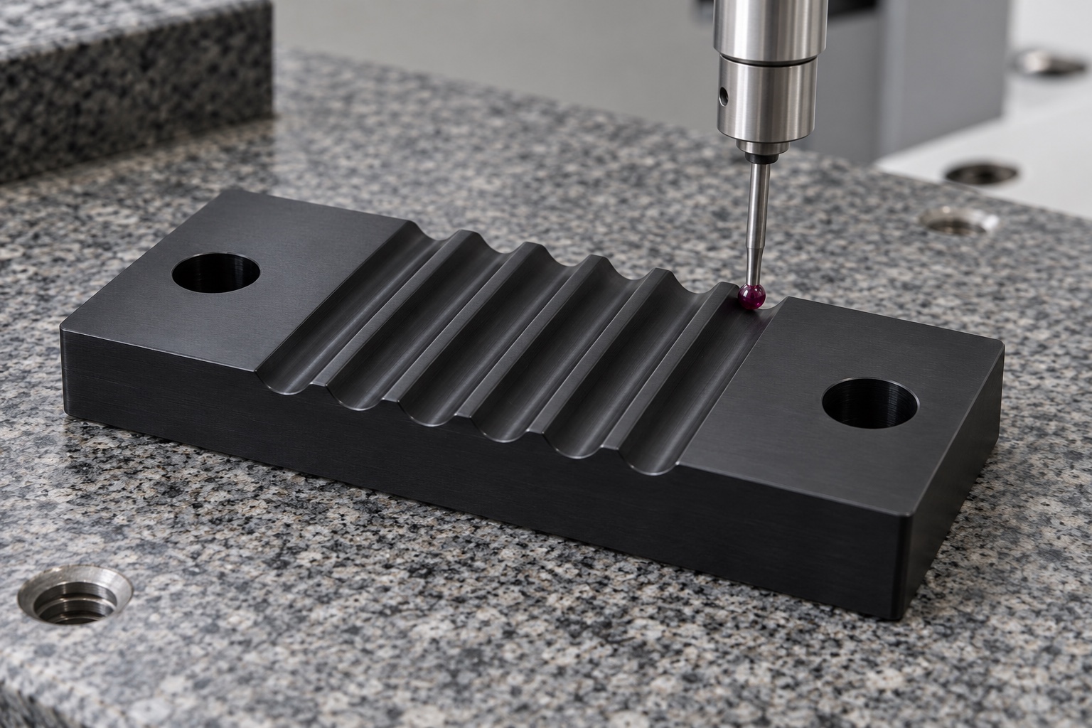
Map the approved profile, pitch relationships, depth, base contact and hole positions to suitable methods before manufacture. Review access to narrow features and whether an optical or contact method is appropriate. Record measuring force, support and any necessary conditioning for the selected polymer. Outside dimensions alone cannot verify the controlled belt interface. A successful sample fit should not silently replace inaccessible measurements. Unloaded component acceptance and an installed clamp condition may have different purposes, so define their scope separately in the inspection plan.
Treat fastener installation as an assembly requirement
The equipment design should define approved hardware, mating plate, installation procedure and any relevant tightening requirements. The CNC supplier should not publish a generic torque value or assume that tighter screws improve every clamp. Excessive or uneven compression can change the installed relationship, but the actual acceptable condition must come from the responsible design. Preserve the distinction between component geometry and assembly setup. A modified washer stack, substitute belt or extra adhesive should be reviewed and documented rather than becoming an unrecorded response to an unsuccessful demonstration.
Keep retention and motion testing separate
An agreed assembly demonstration may examine seating and visible engagement with identified belt, clamp and carriage revisions. It does not independently establish pull-out resistance, cyclic durability, belt damage behavior, positioning accuracy or equipment safety. These require separately defined loads, conditions and evaluation procedures. Do not infer working capacity from a static hand pull or transfer another belt family's rating to the custom interface. Keep trial components traceable and incorporate authorized changes into released requirements instead of preserving an undocumented hand-adjusted clamp as the production master.
Protect grooves and keep belt identity visible
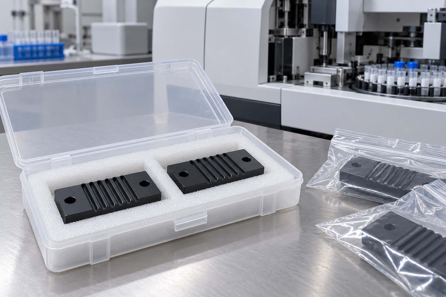
Separate finished clamps so neighboring edges and loose hardware cannot rub the grooved region. Support the base without bending the part under packaging pressure. Protective materials should match the agreed cleaning scope; ordinary transport bags are not sterile barriers. Preserve material, lot, profile and revision identification with the shipment. Any sample belts should be separately identified and protected, not mixed into accepted component stock. Receiving staff need enough information to distinguish similar-looking clamps made for different tooth families, widths, mounting arrangements or final inspection conditions.
Create a repeatable belt-specific inquiry
A complete inquiry includes controlled geometry, exact belt documents, mounting and mating-plate information, material grade, final condition and inspection deliverables. Identify optional demonstrations and keep retention or full-drive qualification separate unless expressly included. Review changed belt profiles, widths, contacts, hardware, cleaning or service conditions before relying on prior observations. Retain authorized revisions rather than reproducing a worn sample. This gives the CNC supplier a defined component scope without asking it to invent an analyzer drive rating or claim that visible engagement proves validated medical equipment performance.
Manufacturer background reference: gates.com.
FAQ
Is equal pitch enough to establish belt compatibility?
No. The actual tooth profile, width, contact geometry and installed arrangement also require definition. Use approved belt and component documents rather than treating a common nominal pitch or a similar photograph as complete evidence.
Does adding grooves prove higher retention?
No. Engagement and loading are design and evaluation matters. The released geometry defines the intended contact, while retention needs its own specified assembly conditions and evidence. Groove count alone is not a working-load rating.
Can black POM be replaced by another black plastic?
Only after authorization under the controlled requirements. Appearance does not establish the grade, properties or suitability of a finished clamp, and material documentation does not replace retention or durability evaluation.
May a belt sample replace profile inspection?
Only within an explicitly approved acceptance method and scope. A sample fit does not automatically verify groove geometry, reference relationships, material identity or unloaded component condition, and its belt revision must remain identifiable.
Does the article give a tightening torque?
No. Hardware, mating components and installation requirements belong to the actual approved assembly. A universal torque value would not establish the correct clamping condition or validate every belt and polymer combination.
What changes need review before repeating production?
Review belt family, width, tooth geometry, engagement, mounting, hardware, polymer and final processing. Keep authorized revisions rather than transferring observations from another carriage or treating an undocumented hand-adjusted sample as the master.

tanghangyun@oemach.com