
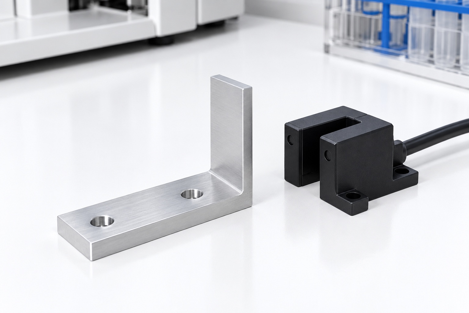
A mechanical target inside the analyzer
A medical laboratory analyzer may use an opaque moving flag to interrupt a slot sensor during carriage travel. The machined bracket provides the target and its mounting interface; it is not the complete detection system. Its geometry should be defined against the actual sensor and mechanism documents rather than a generic photograph. This article addresses CNC component planning, inspection and documentation. It does not specify a universal detection accuracy, stopping position, medical safety function or achieved manufacturing tolerance. Illustrations are concepts, not measured production samples.

Identify the exact sensor and direction of travel
Start with the approved sensor model, installation drawing, target requirements and carriage revision. The manufacturer's selection information distinguishes slot width, body shape and object entry direction; these provide context, not dimensions for an arbitrary custom bracket. Confirm where the sensing aperture lies and how the vane approaches it in the real installation. Electrical output, response behavior and controller interpretation need their own definitions. A bracket that enters the mechanical slot is not automatically a qualified target for every optical configuration or operating condition.
Relate the vane to functional mounting references
The mounting foot establishes the relationship between the carriage and the upright vane. Identify the locating contacts and fastener-clearance features separately, and define the relevant vane position and orientation from those references. Overall height alone may miss a shifted sensing edge or a tilted face. A raw saw-cut edge should not become the inspection datum merely because it is accessible. Resolve inconsistent model and drawing references before machining so production does not choose a convenient but functionally unrelated coordinate system.
Control the edge that crosses the aperture
Distinguish the leading sensing edge, the opposite edge and the vane's broad faces. Their required shape and position come from the actual detection arrangement. Do not assume that a nominally rectangular tab defines the whole optical target. Specify edge treatment without allowing an uncontrolled chamfer to shorten the intended opaque region. Any proposed radius must be reviewed against the installation. A successful single hand movement through a sensor does not replace the released edge geometry or demonstrate repeatable switching throughout the analyzer's working conditions.

Review clearance over the complete motion envelope
Check vane thickness and lateral position against the sensor slot and neighboring hardware through the approved movement range. Include assembly variation, authorized adjustment and any conditions the designer identifies as relevant. The CNC supplier should not invent a universal clearance or use contact with the sensor body as a locating method. A collision observed in a trial needs documentation and review before cutting the vane thinner. Confirm that screw heads and tools can also be installed without changing the controlled mounting relationship.
Select material and final surface requirements explicitly
The order should identify the approved aluminum grade, condition and evidence. Material identity should remain traceable from stock to shipment. If coating or another treatment is required, define its coverage, masking and final inspection state rather than inferring it from a silver illustration. Optical behavior belongs to the actual sensor and target evaluation. Neither aluminum identity nor a dark-looking finish alone proves switching performance. The supplier must not substitute another material or surface process merely because a prototype happens to interrupt a beam.
Support the upright vane during CNC manufacture
A thin upright feature can become less supported as surrounding stock is removed. Plan the machining sequence and workholding so the mounting foot and vane retain their required relationship after release. Keep fixture contacts free of chips, and avoid forcing a flexible feature into a temporary straight condition. Tool access to the inner corner should be reviewed before production. A different corner radius or supporting rib is a design change when it affects the released geometry, not an automatic shop-floor improvement.
Finish edges without changing the target
Inspect the vane perimeter, mounting-hole exits and the internal foot transition for unwanted sharp edges or attached material. Use the approved edge requirements to distinguish deliberate geometry from burrs. Aggressive polishing should not conceal damage or move a sensing edge. Cleaning follows the purchased scope, and any later treatment needs corresponding final-condition checks. A visually attractive bracket does not establish a particle limit, electrical behavior, corrosion result or sterile status. Those claims require separate requirements and evidence rather than assumptions about a smooth machined surface.
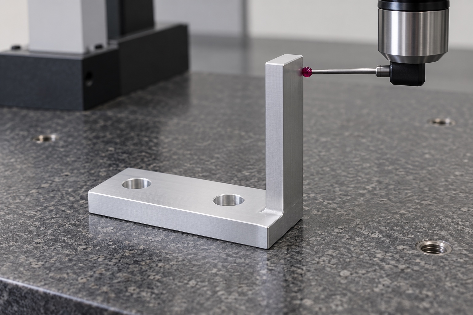
Plan inspection around accessible functional features
Map drawing characteristics to suitable dimensional methods using the approved foot and locating references. Address vane thickness, edge location, face orientation, hole positions and other controlled relationships as required. Select a probe or optical method that can reach the feature without bending it. Record support and final-treatment condition. A report containing only outside dimensions and hole diameters may omit the target-defining geometry. Resolve inaccessible measurements before production instead of silently accepting them through a sensor demonstration or an unrelated height measurement.
Separate a fit trial from detection validation
An agreed fit trial can examine seating, screw access and mechanical clearance with identified sensor and carriage revisions. Record the actual configuration and unexpected contact before making changes. Detection threshold, repeatability, response timing, contamination effects and control-system behavior need separately defined evaluation. A single observed switching event does not establish these results or a medical safety claim. Keep trial parts identifiable so an adjusted demonstration bracket does not become an undocumented production master or a universal gauge for other sensor models.
Protect the vane during handling and transport
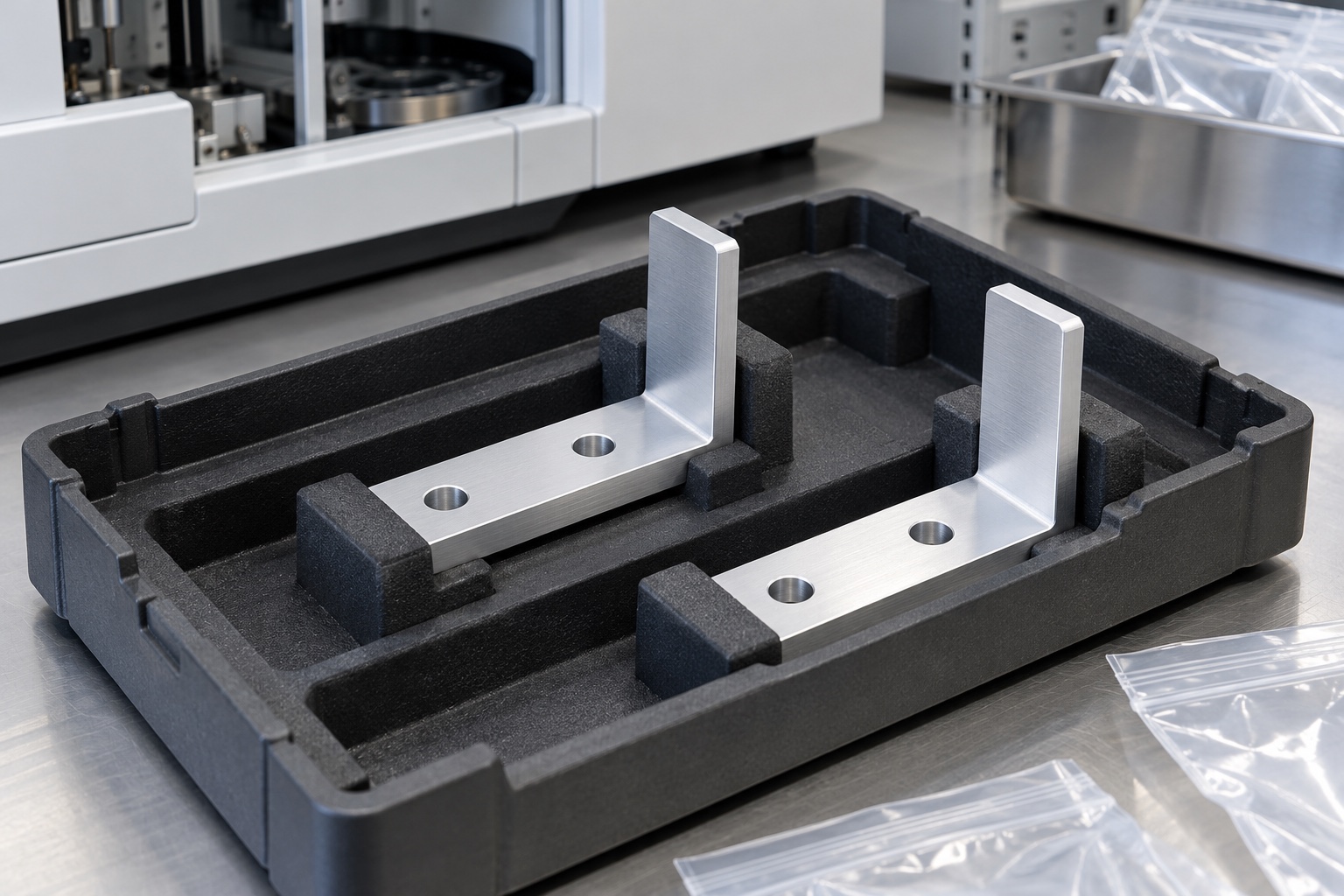
Support the bracket at its mounting foot and prevent neighboring parts from pressing against the upright target. Packaging must not use the vane as a convenient clamping surface. Separate loose fasteners and protect accepted edges from rubbing within the agreed cleaning scope. Ordinary bags or protective trays do not imply sterile supply. Preserve material, treatment and revision identity with the shipment. Receiving personnel should distinguish released brackets from prototypes and from visually similar flags intended for another sensor aperture, entry direction or carriage installation.
Preserve a sensor-specific inquiry package
A useful inquiry contains the model and drawing, exact sensor documents, carriage references, motion envelope, material condition, final process and inspection deliverables. Identify optional fit work and keep electrical or detection qualification separate unless explicitly included. Incorporate authorized prototype changes into revised documents. Review altered sensor models, mounting stacks, coatings, travel or control requirements before reusing previous observations. This supports a traceable mechanical target without asking a CNC supplier to invent sensing requirements or claim that component acceptance validates the analyzer's positioning system.
Manufacturer background reference: components.omron.com.
FAQ
Does a flag that fits the slot prove detection accuracy?
No. Mechanical clearance and dimensional inspection do not establish switching threshold, repeatability, timing or controller behavior. Those require separate evaluation with the actual sensor, target, installation and operating conditions specified by the responsible equipment team.
Which bracket reference should locate the sensing edge?
Use the released functional mounting and locating references. An accessible raw edge or overall height alone should not replace the drawing-defined relationship between the carriage, vane and sensing aperture.
May the vane be thinned after an interference trial?
Only through an authorized change. First document the sensor, carriage, bracket revisions and interference conditions. Informal filing should not become the production baseline or silently change opacity, stiffness, edge location or installation clearance.
Does the image specify a bare aluminum finish?
No. Images illustrate geometry only. The order defines material condition, treatment, masking and inspection state. Any effect on optical detection needs evaluation with the actual target and sensor rather than a visual assumption.
Can a sensor trial replace component measurement?
Not unless the approved acceptance plan explicitly assigns that method and scope. A fit demonstration has its own limitations and does not automatically verify vane orientation, target-edge position, mounting geometry or final surface requirements.
What changes need review on a repeat order?
Review sensor model, aperture, entry direction, carriage contacts, vane edges, mounting stack, material and final treatment. Retain controlled revisions rather than reproducing an undocumented hand-adjusted sample or transferring another sensor's switching observations.

tanghangyun@oemach.com