
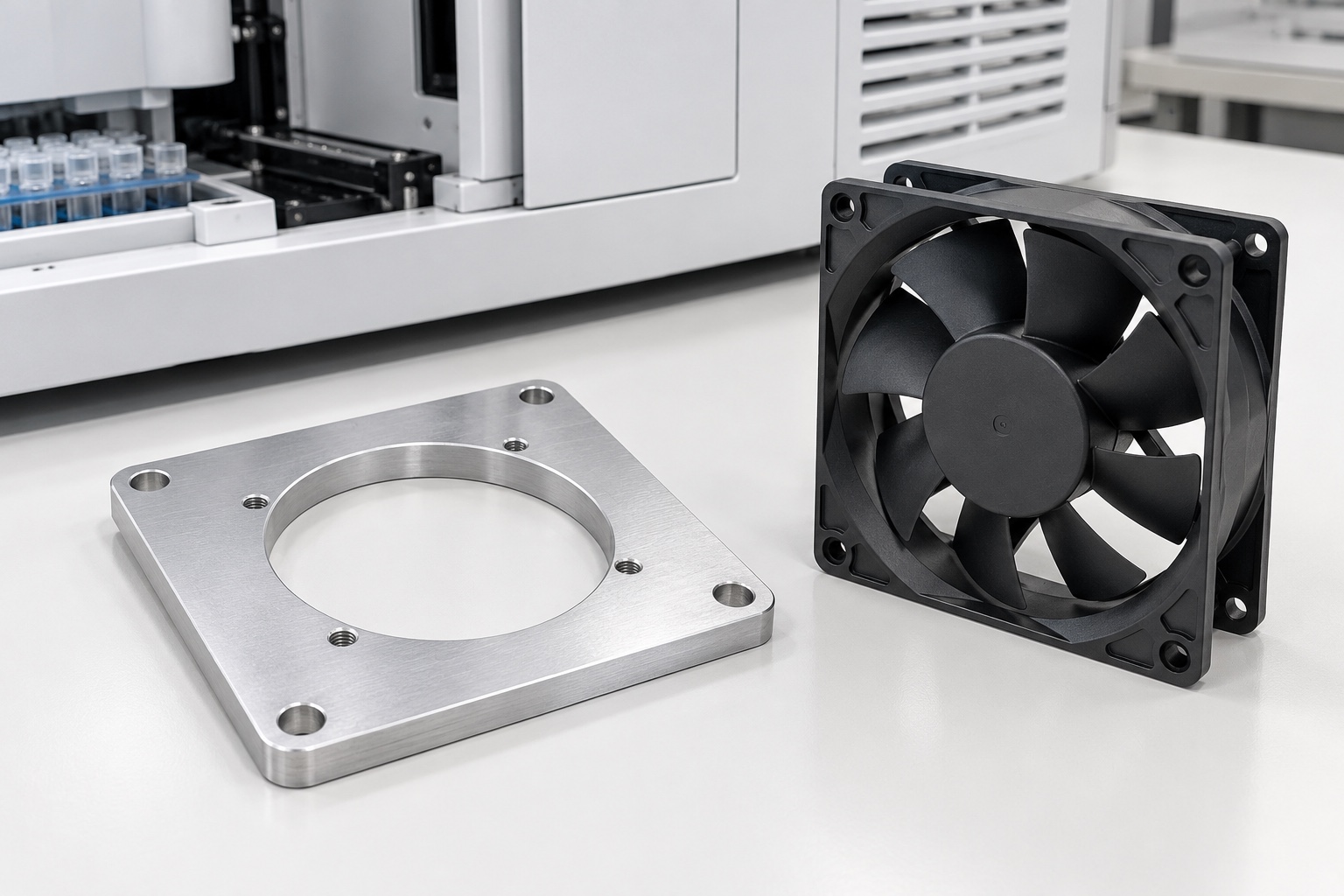
A representative proposed adapter plate
This example considers a proposed one-piece 6061 aluminum fan adapter for medical laboratory equipment. It has a square outline, circular through opening, four smaller fan mounting holes and four separate enclosure mounting holes. It illustrates a possible CNC manufacturing workflow, not a real customer delivery or qualified cooling assembly. The images are component concepts, not photographs of measured production results. Final material condition, fan interface, hardware, finish and acceptance requirements would need approved project documents. No achieved tolerance, cooling capacity, noise result, certification or device-level safety outcome is claimed.

Review the two interface packages
The proposed order would begin with a controlled adapter drawing and model, actual fan documentation, enclosure interface and approved fastening stack. The review would distinguish fan contact from enclosure contact and identify areas intended to remain clear. A generic catalog picture would not define the complete installation. Conflicting mounting dimensions or unclear screw arrangements would be resolved in writing before manufacture. The purchased scope would separate component machining, an optional mechanical fit trial and independent thermal, vibration, guarding or equipment-level assessments assigned to the responsible medical equipment program.
Preserve aluminum stock identity
The material order would identify the approved 6061 condition, stock form and required documentation. Lot identity would remain associated with cut blanks through machining, final treatment and shipment. A visually similar aluminum offcut would not automatically be accepted as equivalent. The supplier would review stock allowance and support for the narrow frame left by the large opening. Proposed substitutions would require authorization before use. Material identity would support the specified component order, not become a general claim about corrosion resistance, electrical behavior or fitness for every medical equipment environment.
Establish references before opening the center
Initial operations would establish the mounting faces and reference features needed to relate the opening and hole patterns. Workholding would support the plate without forcing it into an artificial shape. The route would consider changing stiffness as central material is removed, with controlled transfers between supported setups. Chips at fixture contacts would be removed before referencing. Intermediate checks could confirm the process sequence but would not replace final inspection in the specified released condition. The intended result would be repeatable geometry, not one apparently flat sample held under excessive clamping pressure.
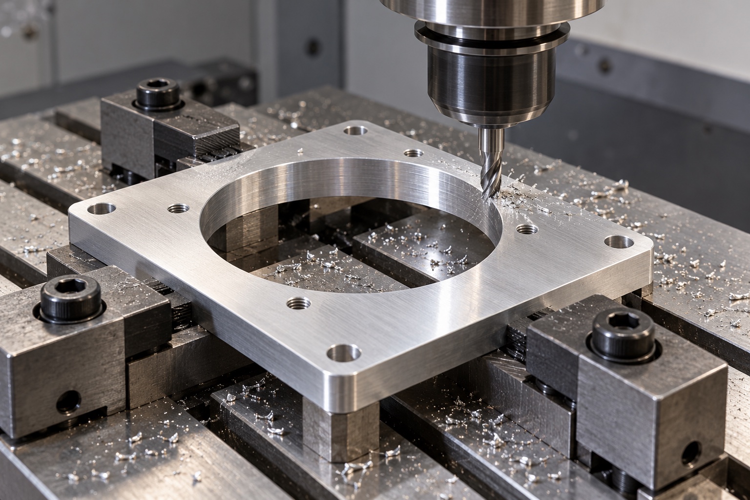
Machine the circular opening from controlled references
The aperture would follow approved size and location requirements relative to the mounting interfaces. Tool access and the final edge transition would be reviewed before production. An outside raw edge would not silently replace the drawing's functional reference. The supplier would not enlarge the opening informally to match an unidentified fan sample. If the design team authorized a change, the revised model, drawing and inspection plan would record it. Machining would establish defined geometry without treating a larger hole as evidence of improved cooling in the actual analyzer enclosure.
Produce the separate mounting patterns
The smaller fan holes and outer enclosure holes would follow their specified references, hole forms and hardware arrangement. The review would identify whether a given hole was threaded or clearanced rather than relying on appearance. Thread identity, engagement and any recesses would be controlled documents, not shop assumptions. A mounting conflict would be clarified before production decisions. Any authorized change to the fan, screws or plate interfaces would enter the revision record so subsequent batches would not depend on an undocumented hand-fitted prototype or memory of the first installation.
Finish edges without changing seating geometry
The finishing process would inspect both sides of the opening, hole exits and outer boundaries for attached material and unwanted sharp transitions. Removal would preserve approved face contacts and hole geometry. Excessive rounding or uncontrolled polishing would not be used to hide a seating discrepancy. Markings would remain in authorized locations. Cleaning would follow the purchased scope, and damage to a mounting face would be treated as a component issue rather than hidden under a fan or a protective film. Visual cleanliness would not establish sterile supply or a quantified particle requirement.
Apply only the approved surface process
If anodizing or another finish were required, the supplier would agree process documentation, masking and final-condition inspection before treatment. Functional threads, contacts and any bonding regions would follow the actual equipment design. A finish change would not be dismissed as cosmetic when it affected acceptance requirements. Bare silver illustrations would remain geometry concepts rather than the released finish specification. Treatment records would stay associated with the material lot and drawing revision, preserving the distinction between component manufacture and separately demonstrated electrical, environmental or thermal behavior in installed equipment.
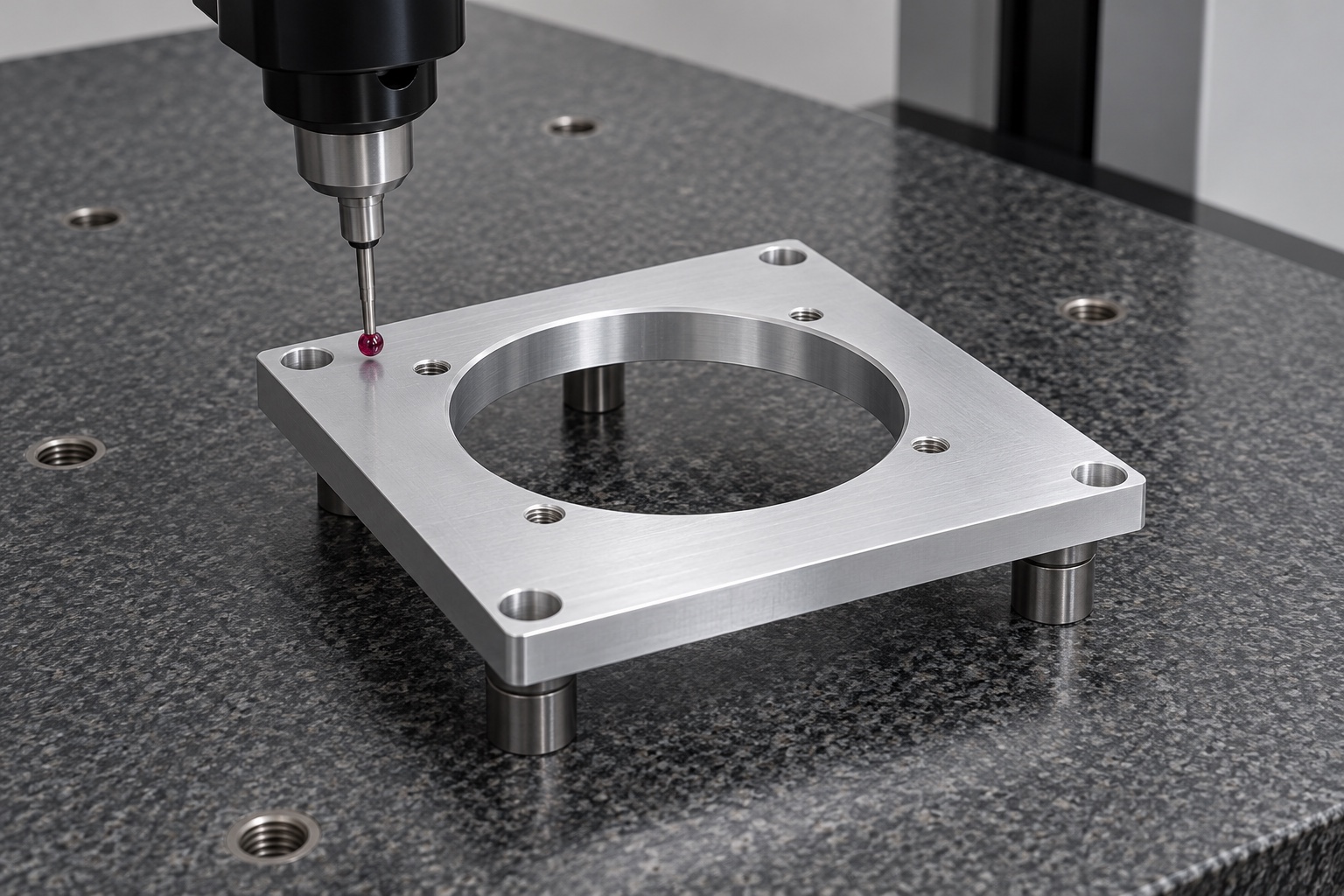
Prepare drawing-linked first-part evidence
The report would identify the approved revision, material lot, numbered characteristics and inspection methods. Evidence would address the specified opening, separate mounting patterns, thickness and seating-face relationships in the agreed support condition. No numerical results are supplied because this representative example has no manufactured sample or measurement record. A report listing outside dimensions alone would not verify the complete controlled interface. Any inaccessible feature or ambiguous requirement would be resolved before production rather than replaced with a convenient unrelated measurement or an undocumented fan fit check.
Define an optional mechanical fit trial
An agreed trial could check seating, orientation, fastener access and specified clearances using identified fan and enclosure components. Their revisions, hardware and installation conditions would be recorded. Unexpected contact would be documented before changing the adapter or frame. A successful trial would not demonstrate cooling, acoustics, vibration life, protective guarding or medical equipment safety. Such evaluations would require their own approved procedures and criteria. The demonstration sample would remain traceable instead of becoming an informal production standard that silently replaced drawing-defined dimensional acceptance for later orders.
Package without bending the remaining frame
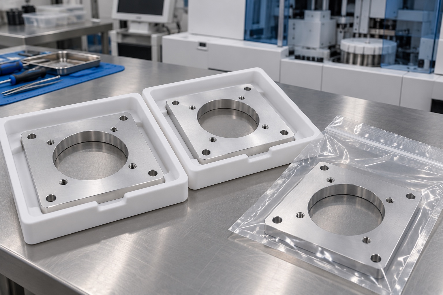
Finished adapters would be supported individually or separated so contact faces and opening edges could not rub neighboring plates or loose screws. Packaging pressure would not bend the narrow frame. Protective materials would suit the agreed cleaning requirements without implying sterile delivery. Material, finish and revision identification would remain with the shipment. Any trial fan or mounting hardware would be identified separately. The receiver would be able to distinguish accepted production adapters from prototypes and similar plates intended for different fan frames, gasket stacks or enclosure mounting interfaces.
Release a controlled repeat-order definition
The proposed manufacturing record would retain the approved drawing, model, stock evidence, process route, finish, inspection requirements and any authorized changes. A repeat order would review differences in fan frame, hardware, enclosure, gasket, guard or filter arrangement before relying on previous observations. Component dimensional acceptance would stay separate from the equipment program's thermal and safety evidence. This representative case shows how to make and document a defined mechanical interface, without inventing a real customer, measured capability, cooling improvement or qualified medical equipment result from an illustrative CNC plate.
Manufacturer background reference: www.sunon.com.
FAQ
Is this an actual delivered cooling assembly?
No. It is a representative manufacturing example for a proposed adapter. There is no customer delivery or measured sample record, and no cooling capacity, achieved tolerance, noise result, certification or medical equipment validation is claimed.
What defines the two mounting patterns?
The approved adapter drawing, selected fan documentation and enclosure interface define hole positions, forms and references. Hardware and engagement requirements must be resolved explicitly rather than copied from a fan with a similar external outline.
What would first-part inspection demonstrate?
It would document drawing-defined component characteristics using identified methods and support conditions. It would not demonstrate installed airflow, component temperature, vibration life or equipment safety without separate approved evaluations of the complete assembly.
Can a sample fan replace dimensional inspection?
No. An identified sample can support a separately agreed mechanical fit trial. It does not silently replace required measurements, and observations should not be transferred to another fan revision or fastening stack without review.
Why protect the opening and mounting faces?
Rubbing, trapped hardware or bending can damage the interfaces that inspection accepted. Packaging should preserve those features and part identity while remaining within the purchased cleaning scope, without implying sterile or otherwise specially qualified delivery.
What should be retained for repeat manufacture?
Retain controlled geometry, material, finish, inspection evidence and authorized changes, together with the relevant fan and enclosure configuration. Review changed gaskets, screws, guards or filters before reusing conclusions from an earlier assembly trial or equipment evaluation.

tanghangyun@oemach.com