
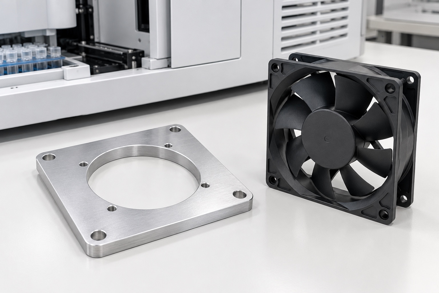
Define the adapter rather than the cooling system
A fan adapter plate connects a selected fan frame to an equipment enclosure or supporting structure. In a medical laboratory analyzer, its opening and mounting contacts are part of an installed airflow arrangement, not a complete cooling solution. Start with the approved fan, enclosure and mechanical interfaces. Do not infer component temperature, ventilation capacity, acoustic performance or equipment safety from an isolated aluminum plate. This article concerns an equipment-side mechanical adapter, not a breathing-gas component, sterile barrier or patient-contact accessory. Responsibility for the complete medical equipment remains with its design program.

Collect the actual fan installation documents
Obtain the selected fan revision, frame drawing, installation instructions and approved hardware before defining the adapter. A generic square outline does not identify whether a mounting screw bears on one flange or passes through the complete frame. SUNON's cited installation example distinguishes flange and rib arrangements and refers users to the relevant model documentation. That context supports checking the real assembly; it does not provide universal instructions for every fan. Use the selected manufacturer's requirements rather than transferring a torque value or mounting method from a visually similar catalog component.
Relate the opening to the installed frame
Specify the circular opening and its relationship to the fan mounting pattern and equipment references. Distinguish an airflow opening from a locating diameter or a deliberate gasket contact. Two separate acceptable hole patterns do not automatically establish correct alignment between fan and enclosure. The approved drawing must identify relevant positions, edge distances and any necessary orientation. Do not enlarge the opening informally because a fan appears to fit. A change can affect support, fastener space and surrounding structure even when the outside square dimensions of the adapter remain unchanged.
Review the full fastening stack
Identify the fan, plate, enclosure, washers, any gasket and the actual fasteners as an assembly. Check which surfaces carry mounting contact and which areas must remain clear. The equipment team must define approved tightening and any retention method. A screw that reaches a threaded hole is not proof of suitable engagement or an undistorted frame. Do not use extra tightening to correct a warped plate or an incompatible mounting arrangement. Document interference or unexpected contact before changing a plate feature, substituting hardware or accepting an unofficial assembly sequence.
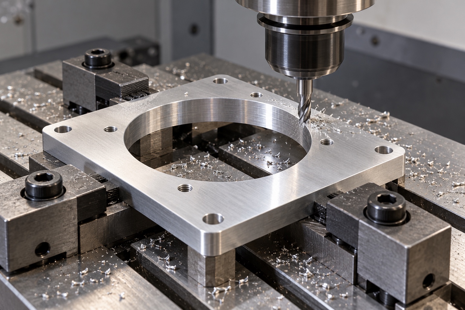
Plan machining around a large central opening
Removing the central opening leaves a relatively narrow frame of material. Review workholding, roughing and finishing so the plate is supported as its stiffness changes. Avoid forcing a plate flat during machining and then assuming that the released component retains the same geometry. Keep chips away from fixture contacts before setup transfers. Tooling and cutting conditions depend on stock, geometry and equipment; there is no universal recipe here. Intermediate checks can help control the route, but final acceptance belongs to the released condition and references specified in the drawing.
Keep mounting faces functionally distinct
The plate may have different contacts on its fan side and enclosure side. Identify face relationships, local seating regions and any approved recesses before choosing the machining sequence. A cosmetically smooth face does not establish the specified flatness or relationship to a mounting pattern. If a gasket is present, its design and compression belong in controlled assembly information. Do not introduce an unapproved groove, adhesive or sealing compound to make a prototype look complete. The machining supplier should manufacture defined interfaces rather than inventing the enclosure's sealing or environmental protection requirements.
Control both opening and fastener edges
Inspect the circular opening, hole exits, outer corners and any recess boundaries after machining. Attached material can interfere with seating, contaminate an assembly or remain hidden beneath the fan frame. Specify acceptable edge conditions without consuming required contact area or changing the opening beyond its approved geometry. Uncontrolled hand polishing is not a substitute for a repeatable finishing process. Keep markings outside functional contacts unless authorized. A finished appearance alone does not demonstrate particle cleanliness, airflow behavior, corrosion performance or readiness for installation into a regulated medical device.
Treat coatings as controlled processes
If anodizing or another treatment is required, identify the approved specification, masking and final-condition inspection. Threads, mounting faces and any electrical bonding interface must follow the actual equipment design, not a general shop preference. Do not infer electrical continuity or insulation from color. The illustrated bare aluminum plate is a geometry concept rather than a mandatory finished condition. A changed surface process can require review of dimensions, contact behavior and assembly requirements. Material and finish documents should remain linked to the exact adapter revision received and inspected.
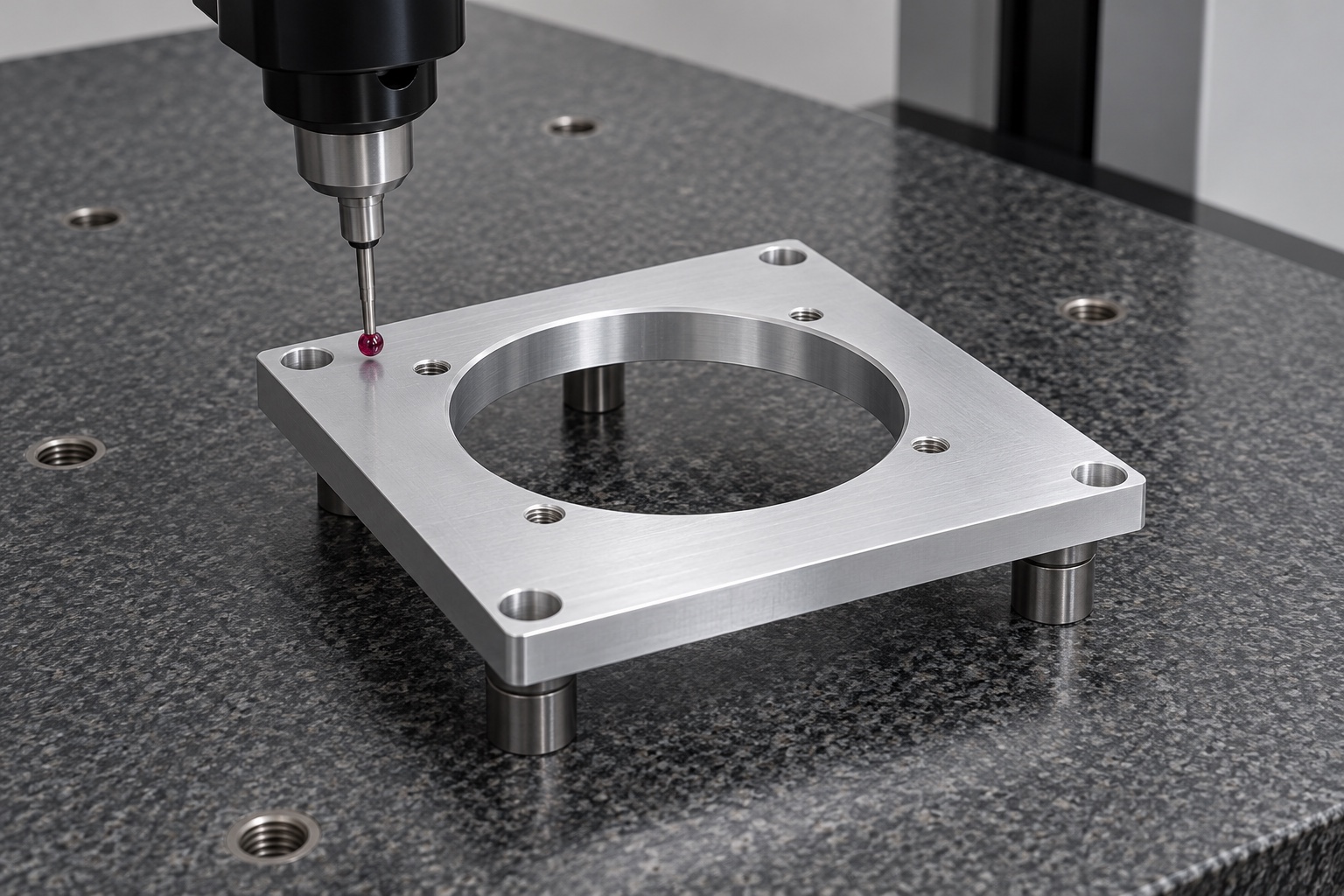
Build a feature-linked inspection plan
Map drawing requirements to appropriate methods for the opening, two hole patterns, thickness and mounting-face relationships. Define support, references and treatment state. Measuring only outside dimensions does not verify an adapter whose function depends on a centered opening and separate interfaces. Resolve inaccessible or ambiguous characteristics before manufacture. A selected fan may be used for an agreed fit demonstration, but its identity and limitations must be recorded. A successful fit does not replace specified dimensional evidence or establish that a different fan revision will assemble in the same way.
Keep fit trials separate from thermal evaluation
An agreed trial can check seating, fastener access, orientation and identified mechanical clearances. Record the fan, adapter and enclosure revisions with the installation conditions. It cannot by itself establish cooling effectiveness, noise, vibration durability, protective guarding or electrical safety. Those questions need separately approved evaluation of the complete equipment configuration. An opening that looks generous may still interact with filters, guards and neighboring parts. The machining report should not claim a thermal result unless a defined test was actually purchased, performed and documented by the responsible program.
Protect thin frames and contact surfaces
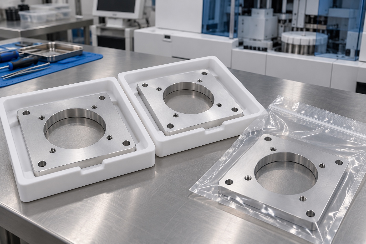
Package adapters so neighboring plates, loose hardware and protective materials cannot rub the mounting faces or damage the opening. Support the plate without bending its remaining frame. Keep identifiers associated with material lot, drawing revision and final finish. Any purchased cleanliness requirement needs an agreed method and verification; an ordinary clear transport bag is not a sterile barrier. Separate trial hardware from accepted production components. Receiving personnel should be able to distinguish the approved plate from a similar adapter intended for another fan frame or enclosure interface.
Make repeat orders configuration-specific
A complete inquiry includes the controlled model and drawing, selected fan documentation, enclosure interface, material condition, final treatment and inspection deliverables. Identify any requested assembly trial and keep thermal or equipment-level qualification separate unless explicitly included. Preserve authorized prototype changes in revised documents rather than a marked sample alone. Review changes to the fan frame, gasket, screw stack, guard, filter or surrounding ventilation path before reusing earlier conclusions. This provides a traceable mechanical adapter without presenting routine CNC manufacture as proof of medical equipment cooling performance.
Manufacturer background reference: www.sunon.com.
FAQ
Does an inspected adapter establish sufficient cooling?
No. Inspection can confirm the agreed component geometry. Cooling depends on the installed fan, enclosure, obstructions and operating conditions, and requires separately defined evaluation of the complete configuration rather than an airflow claim based on a circular opening.
Why obtain the exact fan installation drawing?
Similar frame outlines can have different mounting arrangements and hardware requirements. Use the selected model's documentation and approved equipment stack instead of copying screw engagement or tightening instructions from another fan or an unrelated example specification.
Can the opening be enlarged during prototype fitting?
Only within authorized drawing and process limits. A design change must be reviewed, recorded and reflected in inspection because it can affect support, mounting clearance and surrounding structure even when the plate still accepts the same fan.
Is the outer square sufficient for inspection?
No. The controlled relationship between opening, mounting patterns and seating faces may be more important than the outside outline. Define functional references and accessible measurement methods for the complete drawing requirements before production begins.
Do the silver illustrations specify the final finish?
No. They depict representative geometry. An approved treatment, masking and final inspection must be specified for the actual application, including any dimensional or electrical contact requirements that should not be inferred from surface color.
What belongs in a repeat-order review?
Review the adapter drawing, material and finish together with fan revision, enclosure, hardware and any gasket, guard or filter changes. Earlier mechanical or thermal conclusions should not be transferred automatically to a changed installed configuration.

tanghangyun@oemach.com