
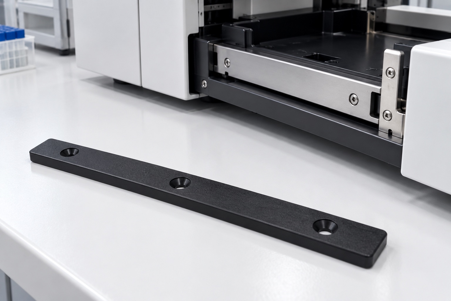
Define the strip within the drawer assembly
A drawer wear strip provides a selected contact surface within a medical equipment service drawer. It is not a complete slide, bearing system, restraint or safety stop. The responsible equipment designer must define how the strip, drawer, support frame and fasteners work together. This article concerns a proposed equipment-side polymer component, not a specimen container or patient-contact item. Start with controlled assembly information and identify which face actually slides, which face is supported and which regions remain clear. A flat-looking bar alone does not define the operating interface or its acceptance requirements.

Obtain the actual mating contact arrangement
The opposite sliding surface, support locations, travel envelope and installation sequence should be identified before machining. A strip that fits an isolated bracket can still contact a screw head or enclosure edge during drawer travel. Specify the relevant assembly revision and any approved lubrication or dry-running condition rather than allowing the supplier to choose one. The equipment team must define the actual load and operating requirements. This article provides no universal allowable drawer load or service-life rating, and a component supplier should not infer them from the length and thickness of a polymer strip.
Specify the actual material grade
Black POM is not a complete purchase specification. Identify the approved grade, stock form and required documentation. The referenced material manufacturer distinguishes a particular black POM-C stock material, which illustrates why a drawing should identify the actual polymer rather than rely on color. Do not transfer a generic material property directly into a life or friction claim for a finished strip. The responsible program must evaluate the real mating material, loading, environment and cleaning process. Preserve lot identity and require approval for any proposed substitution before it enters production or assembly.
Relate thickness to the installed contact stack
The functional contact height may depend on the sliding face, mounting face, local support and fastening arrangement rather than overall thickness alone. Define the relevant geometry and inspection condition. If a requirement applies in the free state, say so explicitly. A different installed or loaded condition needs its own defined method and acceptance meaning. A fixture must not force a bowed strip flat and then present the result as its free geometry. The designer should identify the actual functional references rather than assign equal importance to every outside edge because it appears in a model.
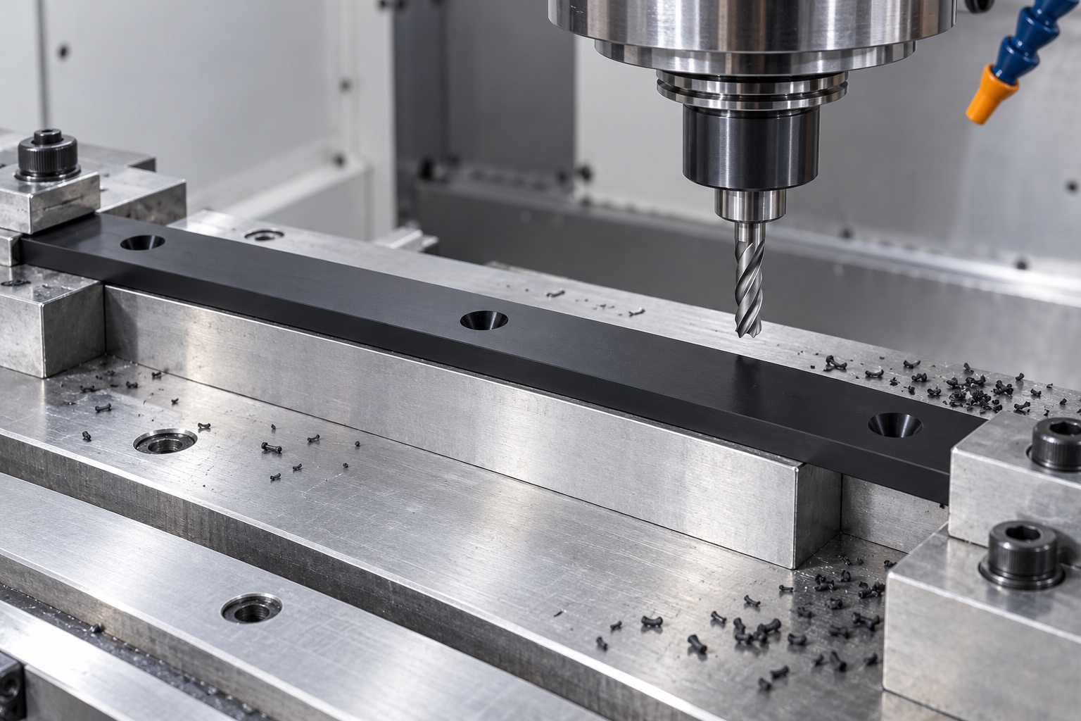
Keep fasteners below the intended sliding path
Recessed mounting features must suit the approved screw geometry and installation arrangement. A hole diameter does not define head seating, recess depth or clearance to the moving surface. Review the entire fastener and access path before production. State the required relationship to the sliding face instead of asking an operator to countersink until the screw looks low enough. This article prescribes no universal tightening torque. The equipment team must determine installation requirements, and changes to screws or recesses should be reviewed before carrying an earlier assembly conclusion into another drawer configuration.
Support long geometry during machining
A narrow strip can respond to local clamping and material removal. Plan broad support, reference transfers and cutter access so the sliding and mounting faces remain related without artificial bending. Control chips and debris at fixture contacts. Cutting conditions depend on polymer grade, stock history, tooling and actual geometry; a universal speed or clamp force is not responsible guidance. Intermediate checks can help confirm the route, but final acceptance must address the completed component under the specified measurement condition. A part that appears flat only inside a fixture is not necessarily an acceptable finished wear strip.
Finish sliding edges and fastener transitions
Examine the ends, long edges, recess transitions and hole exits for attached polymer material or unintended sharp regions. Define an edge condition that preserves the approved contact area. Uncontrolled scraping, heat smoothing or polishing should not become an undocumented way to make the drawer move. Keep markings and labels away from sliding contacts unless approved. Surface appearance can complement inspection, but does not establish a verified texture or abrasion life. Cleaning should follow the material and purchase requirements without leaving uncontrolled residues or disguising damage to a functional mounting or sliding face.
Measure without imposing a misleading shape
The inspection plan should state support locations, measuring force and any required environmental conditioning. A thin polymer feature can be distorted during measurement, so the method must represent the drawing-defined condition. Map thickness, mounting geometry, recess requirements and relevant face relationships to appropriate methods. A report of overall length and hole spacing is incomplete if the sliding interface depends on other controlled features. Resolve inaccessible or ambiguous measurements before production. An installed sample can support a separately defined assembly check but should not silently replace the required component inspection and its documented references.
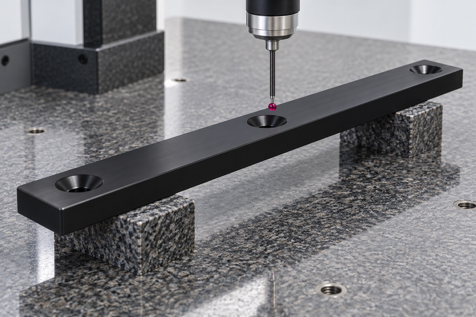
Separate travel checks from life qualification
A controlled assembly trial may check seating, tool access and agreed clearances through a defined travel. Record the strip revision, mating surface, fasteners, support and installation condition. One smooth hand-operated movement does not establish friction under load, wear rate, noise, particle generation, durability or equipment safety. Those matters require separately approved procedures and criteria for the real application. If an unexpected contact appears, document it before changing the strip or its mount. Do not transfer a demonstration result to another mating surface or lubricant merely because the strip's outside dimensions remain unchanged.
Define cleanliness and maintenance boundaries
A clean appearance is not proof of sterile supply or a quantified cleanliness level. Specify any purchased criterion and its verification rather than relying on a photograph or packaging style. The equipment team must define the approved cleaning and maintenance process in the actual operating environment. Do not assume every POM grade tolerates every chemical or that a wiped strip will retain the same contact behavior indefinitely. If lubrication is part of the design, its identity and application belong in the controlled assembly information rather than being introduced as an unrecorded machining-shop preference.
Protect the sliding face during transport
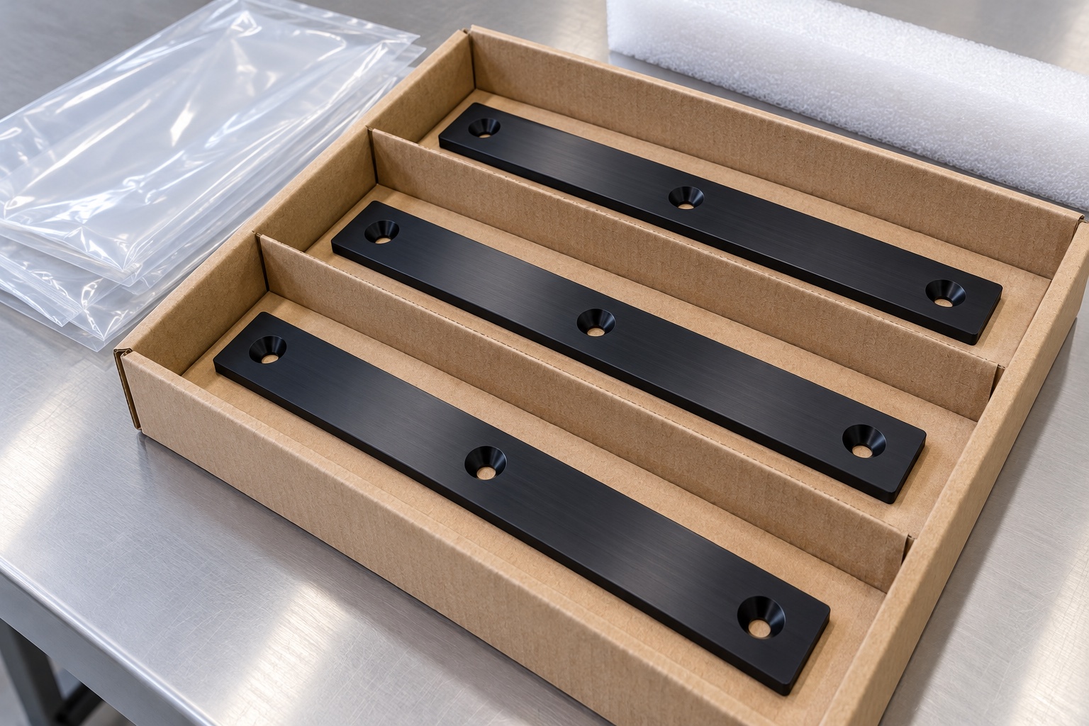
Package strips separately or support them so their contact faces cannot rub neighboring components. Avoid bending pressure, stacked fastener hardware or unapproved adhesive on the sliding surface. Protective materials should suit the agreed cleaning scope and preserve part identity. Keep any assembly samples identified as trial articles rather than treating them as qualified equipment. Material grade, lot and revision records should remain associated with the shipment. The recipient should be able to distinguish the accepted production strip from a prototype, a substituted polymer or a similar part made for a different drawer assembly.
Make repeat production configuration-specific
A complete inquiry includes the approved model and drawing, material grade, mating contact information, support arrangement, fasteners, final edge requirements and inspection deliverables. Identify any assembly trial and keep wear-life or device-level qualification separate unless explicitly defined. Incorporate authorized prototype changes into controlled documents. Review altered screws, support spacing, mating materials, lubricants or cleaning conditions before reusing previous conclusions. This turns a simple wear strip into a traceable manufactured interface with clear evidence, without inventing drawer load capacity, maintenance intervals or medical equipment reliability from an individual polymer component alone.
Manufacturer background reference: www.ensingerplastics.com.
FAQ
Does a smooth drawer trial establish strip service life?
No. It demonstrates only the agreed checks in the recorded configuration. Wear, friction under load, noise, debris generation and durability need separately defined evaluation with approved operating conditions and criteria for the actual drawer assembly.
Why specify a polymer grade instead of black POM alone?
Color and a generic material family do not establish identity or application suitability. State the approved grade, stock form and documentation, and review substitutes before production rather than treating similarly colored blanks as interchangeable wear materials.
Is overall thickness the only important dimension?
Not necessarily. Sliding height can depend on face relationships, local supports, fastener seating and the installed stack. The design must identify its functional references and distinguish free-state inspection from any separately required installed or loaded condition.
Can screw recesses be changed informally?
A change must remain within approved drawing and process limits. Different screws or recess geometry can affect seating and clearance. Authorize design changes and update inspection documents rather than adjusting a prototype until it seems to move smoothly.
What should be recorded for an assembly trial?
Record strip revision, mating surface, fasteners, support arrangement, installation conditions and the explicit travel or clearance checks. Keep the result separate from endurance or safety qualification unless those evaluations are independently defined, performed and documented.
What changes need review on a repeat order?
Review material grade, geometry, mounting, fasteners, mating surface, lubricant and cleaning conditions. Preserve approved revisions and evidence so a previous trial or wear conclusion is not transferred automatically to a different medical equipment drawer configuration.

tanghangyun@oemach.com