
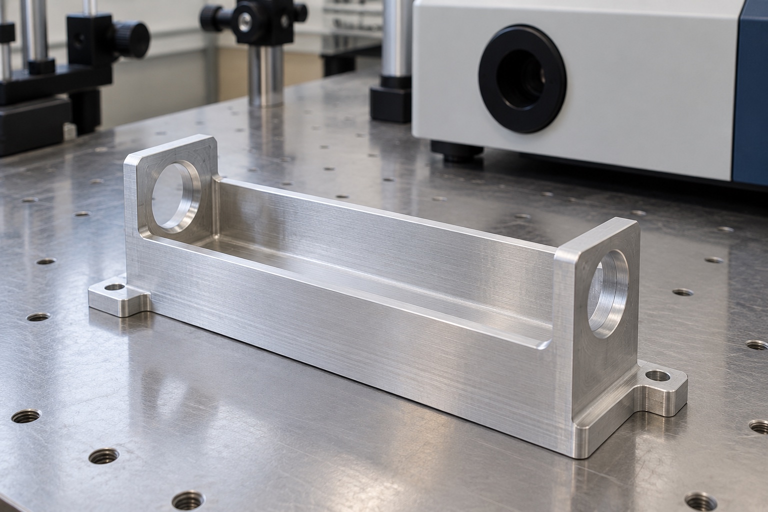
Define the body within the optical assembly
An optical baffle body provides mechanical boundaries and mounting interfaces around part of a diagnostic instrument's optical path. It is not a complete photometer, detector or qualified light-control system. The equipment designer must define how apertures, internal surfaces, covers and neighboring components work together. This article concerns a proposed machined equipment-side body, not a laser safety enclosure or patient-contact component. Begin with controlled optical and mechanical interface documents. A supplier should not infer the required light path, detector clearance or acceptable stray-light behavior from a photograph of an empty metal housing.

Identify clear apertures and controlled references
Specify the approved aperture geometry and its relationship to the mounting plane and locating features. Distinguish the required clear opening from any surrounding recess or assembly access feature. Two acceptable isolated diameters do not establish the complete relationship between the entrance and exit openings. The responsible designer must define the relevant positional and geometric requirements for the actual optical layout. This article provides no universal alignment tolerance. A convenient outside stock edge should not become the acceptance reference if it does not reproduce the position of the installed body within the diagnostic instrument.
Review the complete cover and interface arrangement
An open-top body needs its actual cover and mating arrangement considered before manufacture. Identify mounting contacts, fastener access, cable or component clearances and any deliberately open regions. A cover that fits the outside outline may still contact an internal feature or leave an unintended path through the assembly. The optical component manufacturer cited here describes enclosed lens-tube arrangements, which provides background for considering the complete path rather than treating a bare body as a finished optical system. It does not establish compatibility or performance for this custom component or a particular instrument.
Separate geometric acceptance from optical results
A coordinate report can verify drawing-defined features, but cannot by itself show stray-light rejection, detector response, measurement accuracy or clinical performance. The equipment program must define any optical evaluation, including illumination, installed optics, detector configuration, surroundings and acceptance criteria. Preserve the exact body revision used in that evaluation. A photograph showing no obvious light leak is not a quantified test. A changed cover, aperture, coating or neighboring component may need review even when the exterior dimensions of the housing remain unchanged and the part still bolts into the equipment.
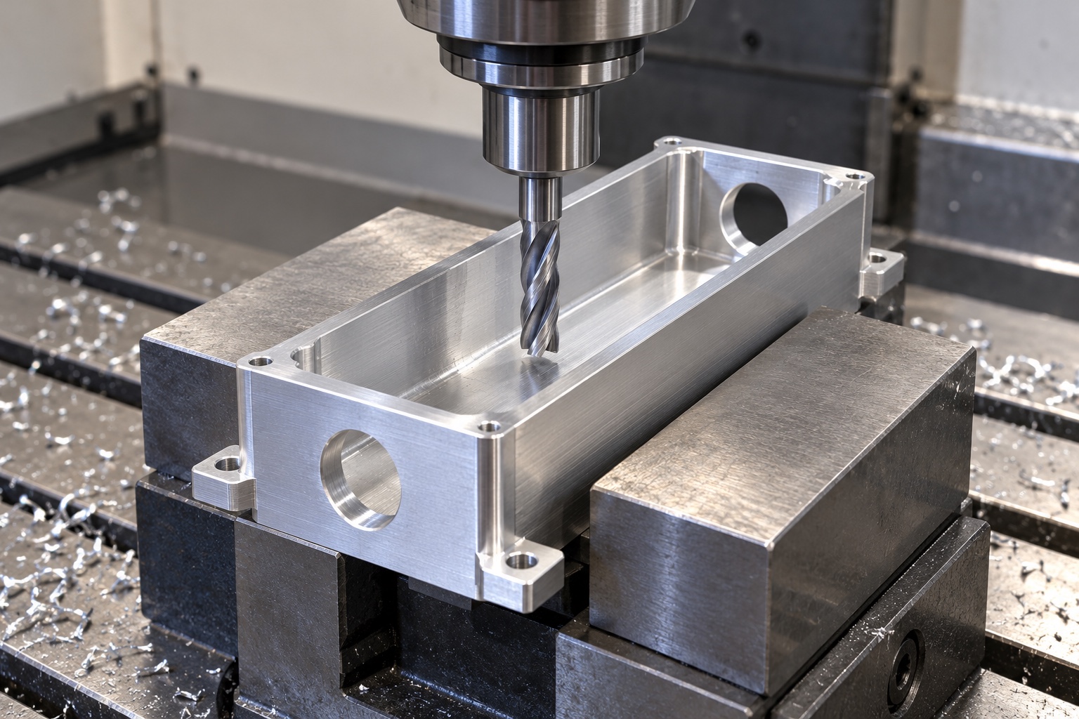
Plan cavity access and internal transitions
Review cutter access, cavity depth, wall thickness and internal corners together. The optical designer must decide whether a proposed radius, relief or transition is acceptable in the actual path. Do not add an undocumented pocket simply because it makes machining easier. Identify regions where attached material or an uncontrolled edge could affect assembly, cleaning or the approved internal envelope. Tool access should be resolved before costing and production. A sample that accepts one loose component does not establish that every controlled cavity feature can be produced, inspected and repeated under the intended manufacturing route.
Support the body as material is removed
Removing a long internal pocket changes the stiffness of the remaining walls. Plan roughing, finishing and setup transfers so the mounting references remain meaningful without forcing the body into an artificial shape. Control chips beneath fixture contacts and protect finished apertures during subsequent operations. Cutting conditions depend on stock condition, tooling, machine capability and actual geometry. No single feed, speed or clamp force is appropriate for every baffle body. Intermediate checks can confirm the sequence but do not replace acceptance of the finished part in the condition defined by the approved drawing.
Make surface requirements application-specific
A dark appearance does not establish a particular optical response. If the design requires anodizing, blackening or another surface process, identify the approved specification, masking, documentation and final-condition inspection. Do not select a finish from appearance alone or copy a catalog claim to a custom housing. Contact surfaces and apertures may require different treatment from surrounding cosmetic areas. The responsible team must evaluate any optical, chemical and cleanliness implications in the actual assembly. Bare silver illustrations show geometry concepts only and should not be interpreted as an approved final optical surface specification.
Finish both visible and hidden edges
Inspect aperture entrances and exits, cavity corners, fastener-hole exits and cover contacts deliberately. A smooth exterior does not prove the internal edges are suitable. Define edge requirements that preserve the approved aperture and contact geometry. Uncontrolled polishing or scraping should not become a hidden method of making an optical assembly fit. Keep markings away from functional surfaces unless authorized. Cleaning must follow the purchased scope and should not mask damaged references. A visually clean cavity is not evidence of a quantified particle level, optical cleanliness classification or sterile supply for a medical application.
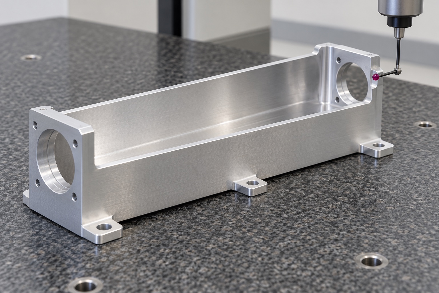
Create a feature-linked inspection plan
Map drawing requirements to methods that can reach the actual apertures, cavity features and mounting references. Record support conditions and the final treatment state. Distinguish geometric form from any separately specified surface texture. An overall length and width report is incomplete when the optical interface depends on internal geometry. If direct access is difficult, agree a reliable method before production rather than substituting an easier unrelated dimension. A mating-component check may complement the plan only when its identity, procedure and acceptance meaning are explicitly recorded alongside the controlled dimensional requirements.
Define limited assembly trials clearly
A documented trial may check component insertion, cover seating, fastener access and agreed clearances with identified approved parts. Record the body, cover and mating-component revisions. Such a trial does not automatically verify optical performance or equipment safety. Unexpected contact should be documented before modifying the body, aperture or cover. An unrecorded hand-fitted sample should not become the production baseline. Keep any optical qualification separate unless its procedure and responsibility are explicitly purchased and defined, and do not transfer observations to another detector or illumination configuration merely because the housing looks similar.
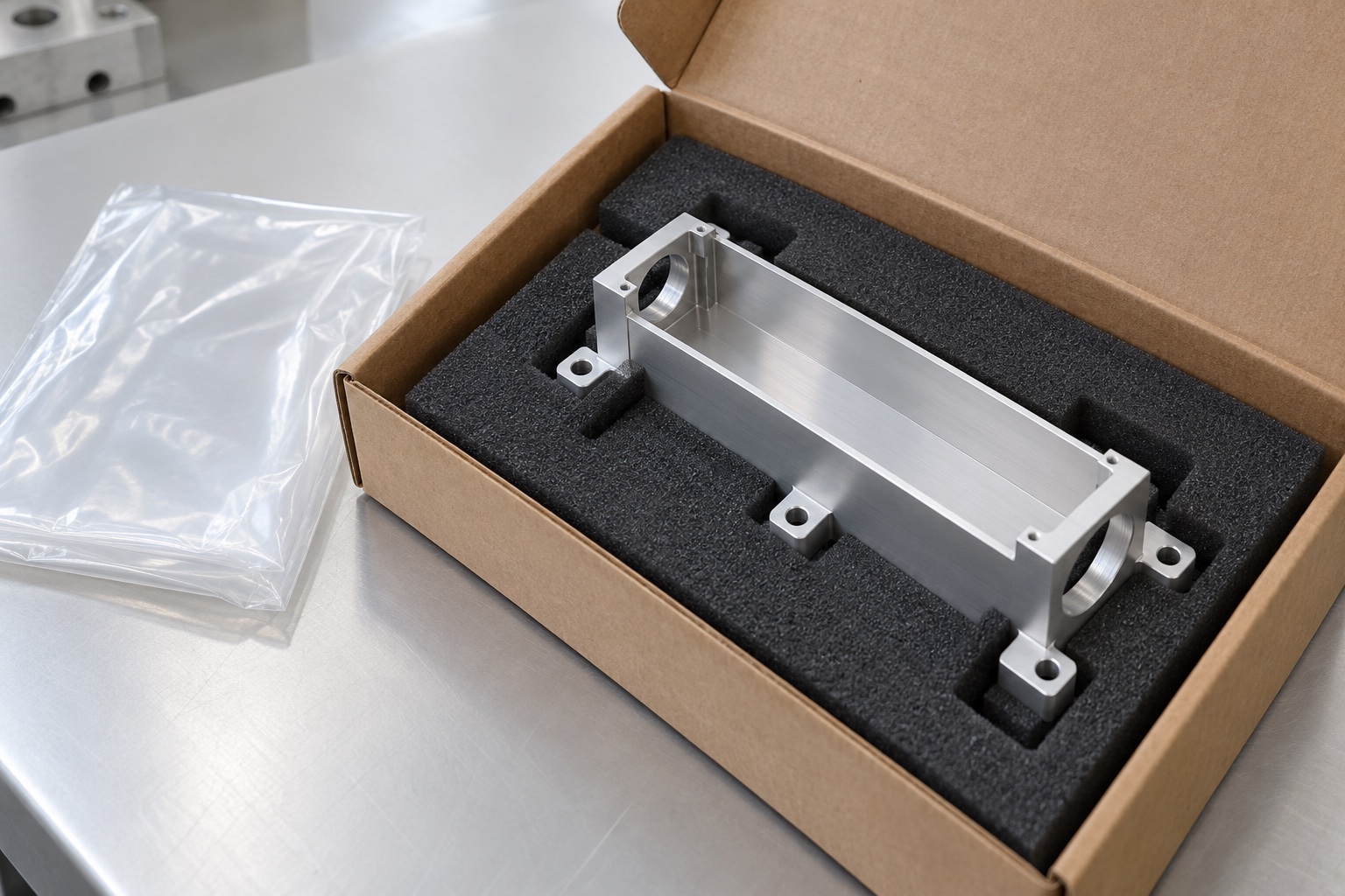
Protect cavities and apertures during delivery
Packaging should prevent neighboring parts or protective materials from rubbing apertures, cover contacts or internal surfaces. Support the base and mounting regions without squeezing thin walls. Avoid unapproved adhesives, fibers or loose residue in the cavity within the agreed cleaning scope. Ordinary transport bags do not establish sterile delivery or quantified optical cleanliness. Any specific criterion needs an agreed verification method. Preserve material-lot, finish and revision information so receiving personnel can distinguish the accepted body from a visually similar prototype or a part made to an earlier internal geometry.
Maintain a complete procurement baseline
A useful inquiry includes the approved drawing and model, aperture and mounting references, mating-component information, material condition, final surface process and inspection deliverables. Identify requested assembly trials and keep optical and device-level validation separate unless explicitly defined. Preserve authorized prototype changes in controlled documents. Review changed covers, coatings, apertures or installed optics before reusing previous conclusions. This makes the baffle body a traceable manufactured interface with clear dimensional evidence, without asking a CNC supplier to invent the instrument's optical requirements or claim diagnostic accuracy from a machined aluminum component alone.
Manufacturer background reference: www.thorlabs.com.
FAQ
Does an accepted baffle body prove stray-light rejection?
No. Dimensional acceptance verifies the agreed component requirements. Stray-light behavior depends on the full optical arrangement and needs a separately defined evaluation with identified illumination, optics, detector, surroundings and acceptance criteria for the actual configuration.
Why are two aperture diameters not enough?
Their relationship to each other and to the mounting references can matter as much as the isolated sizes. The approved optical and mechanical design must define the relevant geometry; a supplier should not invent a universal alignment tolerance from a photograph.
Can a black finish be chosen only by appearance?
No. The responsible team must approve the surface process and evaluate its actual application. A dark-looking surface does not establish optical response, chemical compatibility or quantified cleanliness, and treatment changes may require dimensional and system-level review.
Why inspect internal edges separately?
A clean exterior can hide burrs or attached material at aperture exits and cavity transitions. Define suitable edge conditions and inspection access while preserving the approved geometry, rather than relying on uncontrolled polishing or a successful hand fit.
What can a basic assembly trial demonstrate?
It can show only the agreed insertion, cover seating, access and clearance checks with identified parts. It does not by itself establish detector performance, optical accuracy, light rejection or complete medical-device safety without separate approved evaluation.
What changes require review before repeating manufacture?
Review apertures, cover interfaces, material, coating, installed optics and mounting conditions. Retain approved revisions and authorized prototype changes instead of carrying earlier assembly or optical conclusions into a different equipment configuration without review.

tanghangyun@oemach.com