
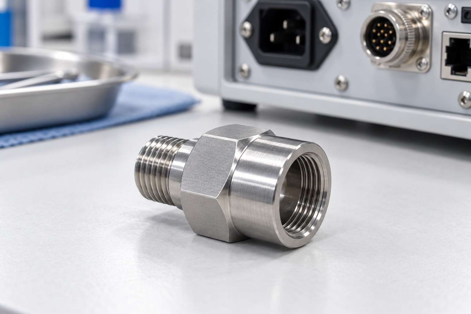
Define the adapter within the cable entry
A cable-gland adapter connects an approved gland interface to a different equipment-side mounting interface. It is only one element of the cable entry, not the complete gland, seal, strain-relief arrangement or enclosure. In medical equipment, its drawing must identify both threaded ends, the cable passage, tool-contact features and the intended sealing arrangement. This article concerns an equipment enclosure component rather than a fluid connection or patient-contact part. The responsible design team must define the complete installation before a machining supplier can interpret the adapter's functional geometry and acceptance requirements.

Identify both threads without assumptions
Specify the thread family, size, pitch or other applicable designation, relevant tolerance requirements and intended engagement for each end. Do not infer equivalence from a similar outside diameter. The referenced cable-gland manufacturer offers adapters for different thread types, illustrating why each interface needs an explicit identity. This article does not prescribe a universal thread pairing. Obtain controlled documents for the gland and panel connection and resolve ambiguous callouts before manufacture. A sample that begins to screw into a part is not enough to establish correct production compatibility or complete thread acceptance.
Separate thread engagement from sealing
A mechanical thread connection and a sealing interface are not automatically the same feature. The equipment design must identify where sealing occurs and which gasket, washer, ring or other approved element is involved. Define its contact surfaces and the relevant final condition rather than expecting the supplier to invent a sealing arrangement. A well-finished thread does not by itself establish ingress protection or a leak rating. Keep installation requirements and component dimensional acceptance separate from the enclosure-level evaluation needed to substantiate any claimed protection of the finished medical equipment.
Review panel thickness and installation access
The complete mounting arrangement determines whether the adapter can be installed and retained as intended. Obtain the panel thickness, mounting-hole geometry, available thread engagement, locknut or other retention details and access for tools. The external hexagon or flats should be related to the approved installation rather than selected solely for appearance. Check surrounding covers and cable connectors as well as wrench movement. A component that fits a loose bench gland may still be unsuitable in a crowded equipment wall. Review the actual assembly sequence before releasing the manufacturing documents.

Keep the cable passage and edges controlled
The adapter's internal passage must accommodate the approved cable and connector installation sequence. Identify the cable-contact regions, internal steps, thread runouts and transitions at both ends. A nominal through-bore diameter does not establish a suitable path if an internal shoulder or burr obstructs installation. Define the required edge condition and verify access to hidden transitions. The supplier should not enlarge a passage informally after discovering that an unapproved connector does not pass. Any accepted geometry change belongs in controlled documents and the corresponding inspection requirements for repeat manufacture.
Specify material and final surface condition
316L may be proposed for an adapter, but the designation is not a universal promise of corrosion resistance, cleaning compatibility or medical certification. Specify the approved material condition and evidence, and review the actual gland, seal and enclosure material combination. A visually similar stainless blank is not automatically equivalent. If passivation or another final process is required, state documentation and final-condition inspection needs. Keep markings outside sealing or cable-contact surfaces unless approved. Neither a polished appearance nor a generic material datasheet proves suitability for the complete equipment's environment or cleaning process.
Plan turning and secondary machining together
The route should preserve the required relationship between both threaded interfaces, the passage and sealing contacts. Plan turning, internal access and any secondary machining of flats without losing functional references. Control chips at workholding contacts and protect finished threads during additional setups. The appropriate tooling and sequence depend on the actual geometry and approved requirements; no single cutting recipe applies to every adapter. Intermediate checks can confirm the process, but final acceptance must address the completed component after any required treatment, not only a partly machined sample that fits one mating part.
Inspect thread features using agreed methods
Define how the specified threads will be evaluated, including suitable gauges and their acceptance meaning. A functional mating trial can complement an inspection plan but does not automatically verify all relevant thread characteristics, engagement length or geometric relationships. Identify thread entries, runouts and reliefs in the drawing review. If a feature cannot be measured reliably with the proposed tools, resolve the method before production. Keep gauge identity and material condition in the inspection record. Do not substitute an unrecorded shop fitting for the controlled requirements simply because it screws in smoothly by hand.
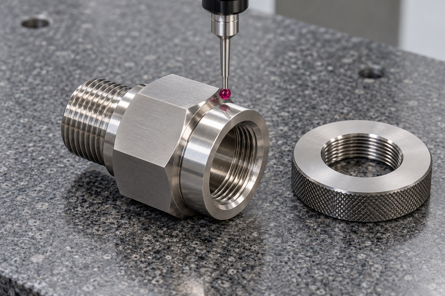
Verify sealing contacts and passage geometry
Map each drawing requirement to a method that can evaluate the actual feature. Depending on the approved design, relevant evidence may include sealing-face geometry, contact widths, passage size and relationships between installation references. Distinguish specified surface texture from geometric form. An overall length and external diameter report is not a complete inspection of a threaded cable-entry interface. Examine internal burrs and transitions deliberately. Record any defined support or final-treatment condition. A dimensional result supports the purchased component scope, not an unsupported conclusion that an assembled enclosure has passed ingress or electrical evaluation.
Define assembly trials without overclaiming
A controlled trial may check thread engagement, tool access and agreed cable clearances with identified components. The responsible team must specify the installation procedure and any tightening conditions; this article supplies no universal torque. Record the adapter revision, gland, seal, panel and retention arrangement. A hand-tight bench assembly does not demonstrate ingress protection, pull resistance, electromagnetic behavior or medical-device safety. Those conclusions require their own approved tests and criteria for the complete configuration. Document unexpected contact before altering the adapter, gasket or mating part and preserve any authorized change.
Protect threads and sealing faces in transit
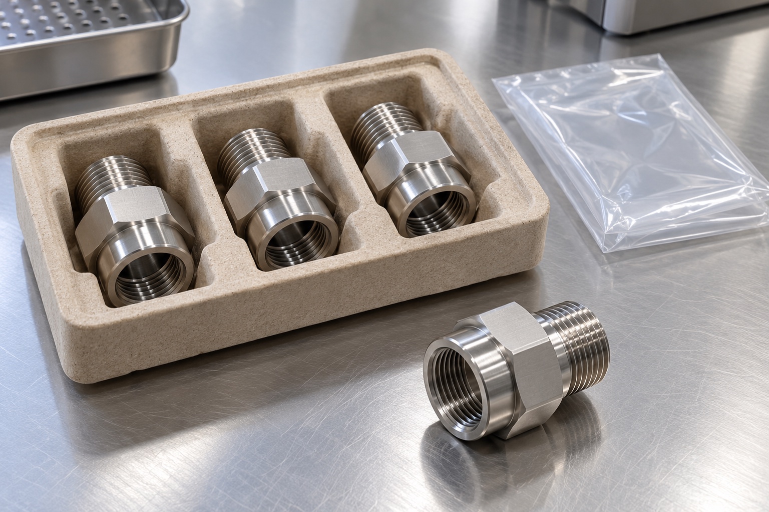
Package adapters so exposed threads, sealing contacts and passage entrances cannot strike neighboring metal parts. Use protection compatible with the purchased cleaning scope and avoid residues inside the bore. Keep any supplied seals or mating hardware identified as approved production items or trial samples. Ordinary protective packaging is not sterile supply or evidence of quantified cleanliness. If a specific criterion is required, define its verification. Preserve material-lot and revision records so receiving personnel can distinguish the accepted adapter from a visually similar thread variant before installation in the medical equipment enclosure.
Maintain a complete repeat-order definition
A complete inquiry includes the approved component drawing and model, both thread identities, gland and panel documents, sealing arrangement, material condition, final process and inspection deliverables. Identify any assembly trial and keep enclosure protection, strain relief and electrical qualification separate unless explicitly defined. Preserve authorized prototype changes. Review modified glands, seals, panels or installation procedures before reusing previous conclusions. The outcome is a traceable machined adapter with defined interfaces and evidence, without asking a turning supplier to invent or guarantee the protection level and safety of a complete medical equipment cable entry.
Manufacturer background reference: www.lapp.com.
FAQ
Does a stainless adapter establish an enclosure protection rating?
No. Protection depends on the complete gland, seals, panel, installation and approved evaluation. Material identity and dimensional acceptance do not establish an ingress rating or replace the responsible equipment program's tests and acceptance criteria.
Can similar thread diameters be treated as equivalent?
No. Identify the approved thread family, size, pitch or other applicable designation, relevant requirements and engagement. A sample that begins to screw into another part does not demonstrate a correct or interchangeable production interface.
Does a correct thread automatically provide the seal?
Not necessarily. The approved design must identify the actual sealing location and elements. Specify the relevant contacts and final condition rather than assuming the thread alone provides a leak barrier or copying a rating from a different catalog assembly.
Who defines installation torque?
The responsible equipment team must approve the actual installation procedure using the selected gland, seal, adapter, panel and retention arrangement. The machining supplier should not invent a universal torque from a material name or thread diameter.
What can a mating-component trial verify?
It verifies only the explicitly agreed thread engagement, access and clearance checks with identified components. Ingress protection, pull resistance, electromagnetic behavior and electrical safety remain separate unless evaluated under defined, authorized and documented procedures.
What must be reviewed before a repeat order?
Confirm both thread identities, revision, material, sealing contacts, gland, panel and inspection plan. Review altered seals, wall thickness, retention or installation procedure before assuming earlier assembly or protection conclusions still apply to the new configuration.

tanghangyun@oemach.com