
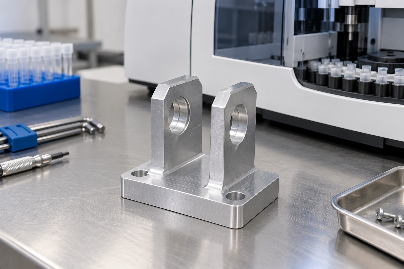
Define the stationary support and its limits
A belt-idler support fork positions an axle or other approved support hardware inside a medical analyzer. It is not the pulley, bearing, belt or complete motion axis. Its drawing should identify the two supporting cheeks, mounting base and interfaces to the selected hardware. The equipment designer retains responsibility for belt selection, loading, tensioning, guarding and motion performance. This article concerns a proposed equipment-side CNC component, not a patient-contact part or a qualified drive assembly. Start with controlled interface documents so that a supplier does not infer the operating system from an isolated fork photograph.

Obtain the complete axle and pulley arrangement
A bore diameter alone does not define the support. Obtain the approved axle geometry, retention arrangement, pulley width, spacers and any bearing interfaces. Determine which faces establish axial location and which require clearance. A fork that accepts a loose sample shaft can still interfere with the installed pulley or fastening tools. Record whether hardware is supplied by the machining vendor or by the equipment team. Unidentified samples should not replace the interface specification, and any trial components should remain distinguishable from approved production parts throughout manufacturing, inspection and delivery.
Relate the axle axis to installation references
Define the mounting plane and locating features that place the fork within the analyzer. Relate the axle bores to those references rather than reporting two independent hole diameters without their geometric relationship. The designer must establish the necessary requirements for the actual assembly; this article prescribes no universal alignment tolerance. If the mounting arrangement permits adjustment, identify the permitted direction and how the final position is established. A convenient rough stock edge must not silently become the acceptance reference when it does not represent the installed component's position.
Separate support geometry from belt-system design
The Gates precision-drive manual treats idler usage as part of drive engineering. That manufacturer context supports reviewing the complete belt layout, not transferring a catalog rating to a custom fork. The responsible team must supply the approved operating arrangement, relevant clearances and any required load evaluation. A dimensionally accepted aluminum support does not establish belt life, positioning accuracy, bearing life or safe speed. Keep these responsibilities visible in the purchase scope. Do not let a drawing of a stationary bracket become an unsupported promise about the analyzer's entire automated motion mechanism.
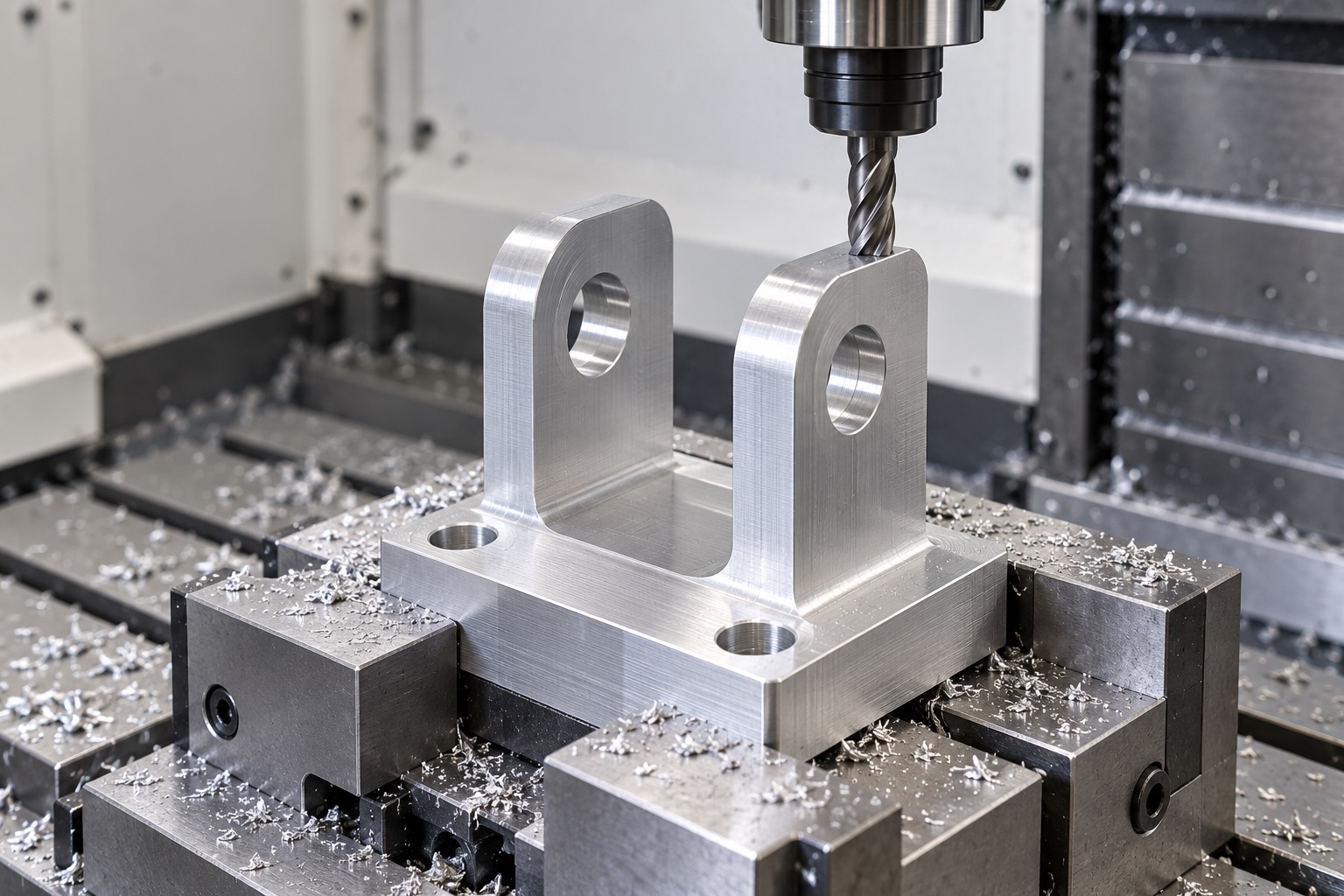
Control cheek spacing and accessible clearances
The open space between cheeks must accommodate the approved pulley, spacers and installation sequence. Identify the surfaces that contact hardware and those that must remain clear during assembly and motion. Check screw-head access, axle insertion and tool withdrawal rather than considering only the nominal width of the pulley. Internal corner radii may affect the usable envelope and should be reviewed before machining. A shop should not remove material informally to fit an unapproved sample. Any accepted relief belongs in controlled geometry and the corresponding inspection requirements for future repeat orders.
Machine the open fork with appropriate support
Removing material between two cheeks changes the stiffness of the remaining shape. Plan roughing, finishing and reference transfers so that the base is supported without forcing the cheeks into an artificial position. Control chips at fixture contacts and consider access to both axle bores before committing to a route. Intermediate checks can reveal an unsuitable sequence but do not replace final inspection. Cutting conditions depend on the actual stock condition, tools, machine and geometry. An article cannot responsibly assign one feed, speed or clamp force to every medical analyzer support fork.
Preserve functional relationships across setups
If different orientations are needed for the mounting base and transverse bores, document how the approved references are transferred. Correctly locating an unfinished blank is not proof that the final axle relationship is correct. The route must preserve the required geometry after material removal and any final treatment. Where several pieces share a fixture, each position needs suitable support and access. Inspection should not rely on bending one cheek until a test axle enters. Such adjustment can conceal an unresolved drawing or process issue and does not establish interchangeable production geometry.
Specify edges and any final surface process
Burrs at bore exits, mounting holes and internal transitions can affect seating or assembly access. Define the required edge condition without indiscriminately rounding contact faces. If anodizing or another treatment is specified, agree masking, documentation and final-condition inspection before manufacture. Coating changes may affect the accepted interface and should not be treated as automatically cosmetic. Keep marking away from functional contacts unless approved. Neither a bright finish nor a clean-looking photograph demonstrates compatibility with cleaning chemicals, corrosion performance, quantified cleanliness or medical-device suitability in the final equipment.
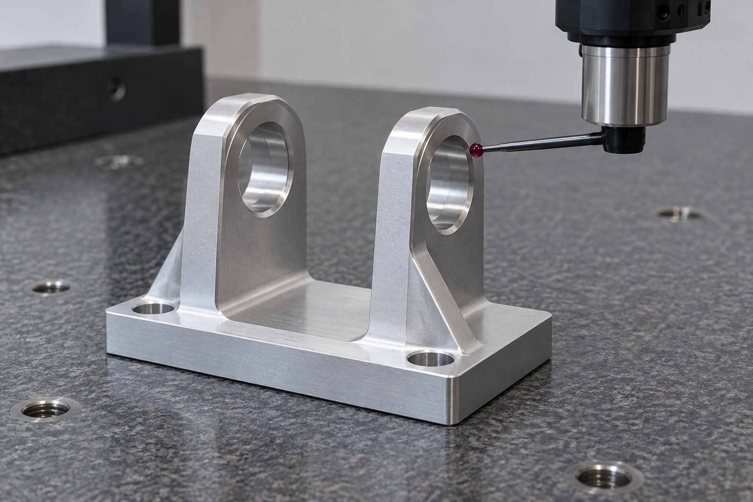
Build a drawing-linked inspection plan
The inspection plan should map numbered requirements to suitable methods and document the support condition. Relevant evidence may include cheek spacing, axle-bore relationships and mounting geometry, depending on the approved drawing. An axle fit check has only the meaning explicitly assigned to it; it does not replace every dimensional or geometric requirement. Resolve inaccessible features before production. If the drawing distinguishes free-state geometry from a specified installed condition, report those separately. A fixture that forces the fork into shape must not create a misleading report of its unrestrained geometry.
Define an optional assembly trial precisely
A controlled trial can check hardware insertion, agreed clearances and access using identified mating components. Record the fork revision, axle, pulley, spacers and mounting arrangement. A simple hand rotation does not demonstrate load capacity, positioning repeatability, wear life or safe machine operation. Those conclusions need separate equipment-level evaluation under approved conditions. If unexpected contact appears, document it before changing the fork or mating parts. An unrecorded hand adjustment should not become the production standard or be transferred silently to the next revision of the analyzer assembly.
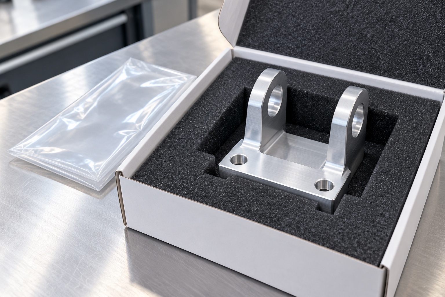
Protect the open geometry during delivery
Packaging should support the base and prevent neighboring parts from striking the cheeks, bore entrances or mounting contacts. Do not use tight packing pressure to squeeze the fork. Keep separately supplied hardware identified and protect finished surfaces from loose debris. Ordinary protective bags and fitted transport supports are not evidence of sterile supply or a quantified cleanliness level. If a specific cleanliness criterion is purchased, define its verification. Preserve material-lot and revision information so receiving personnel can distinguish the accepted component from a visually similar prototype or trial assembly.
Prepare a complete repeat-order package
A useful inquiry includes the approved model and drawing, material condition, axle and pulley documents, mounting references, final process and inspection deliverables. Identify any requested assembly trial while keeping drive qualification separate unless explicitly defined. Preserve authorized prototype changes in controlled documents. Review modified axles, pulleys, belt layouts or installation conditions before reusing previous assembly conclusions. This makes the fork a traceable manufactured interface: geometry and evidence can be purchased clearly, while system loading, motion reliability and medical equipment validation remain with the responsible program and its defined evaluation activities.
Manufacturer background reference: www.gates.com.
FAQ
Does an accepted fork qualify the complete belt drive?
No. Dimensional acceptance covers the agreed component requirements. Belt selection, loads, tension, motion performance and equipment safety require their own approved engineering and evaluation. Do not transfer a catalog pulley rating to a custom support.
Why is the axle diameter not a complete specification?
Cheek spacing, bore relationships, mounting references, retention and the surrounding assembly also matter. A loose shaft that enters both holes does not establish all drawing requirements or confirm clearance for the actual pulley and installation tools.
Can a supplier choose a universal alignment tolerance?
No. The equipment designer must define requirements for the approved drive arrangement. The supplier should review manufacturability and inspection access, and return missing interface information for clarification before committing to production or acceptance criteria.
Can a cheek be bent to pass an axle fit check?
Not as an undocumented acceptance method. Inspection must represent the drawing-defined condition. Resolve geometry or process issues explicitly, and authorize any design change before it becomes a controlled manufacturing configuration for repeat production.
What can an optional assembly trial demonstrate?
It can demonstrate only the explicitly agreed insertion, access and clearance checks with identified parts. Load capacity, life, positioning performance and safety remain separate unless evaluated through defined and documented equipment-level activities.
What should accompany a repeat order?
Retain approved revisions, material evidence, surface requirements, axle and pulley interfaces, mounting information and the inspection plan. Review changed components or installation conditions before assuming that earlier trial observations apply to the new assembly.

tanghangyun@oemach.com