
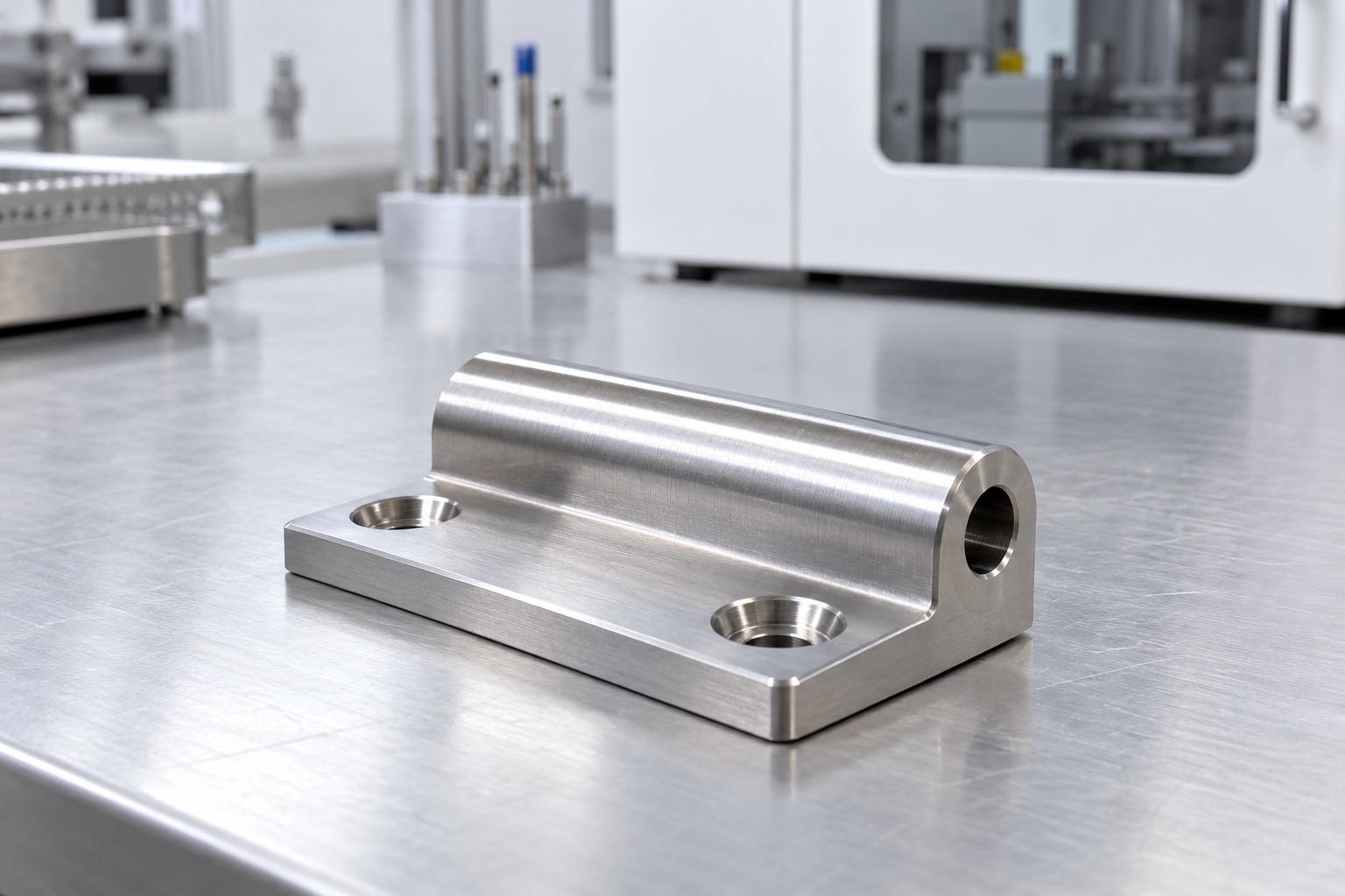
Define the hinge block's boundary
A machined hinge block is one part of a service-door assembly on medical equipment. It may support a pin and provide mounting features, but it is not a complete door system or safety interlock. The equipment designer must define how the door is supported, retained and accessed. This article concerns the mechanical component rather than a certified protective enclosure or patient-support function. Begin by identifying the block, pin, mating hinge elements, fasteners and surrounding enclosure. Their roles must be clear before assigning material, geometry or acceptance requirements to a custom CNC component.

Separate motion support from safety functions
A hinge permits movement; a lock, stop or interlock may perform other functions in the equipment design. Do not infer a safety function from the appearance of a hinge. The referenced manufacturer explicitly distinguishes a hinge version without a safety switch, illustrating why those roles cannot be merged casually. A custom block should not inherit another product's rating or certification. The responsible program must define access protection and any required evaluation for the actual equipment. The machining supplier's scope is the approved component geometry and evidence, not an assumed qualification of the complete service-door arrangement.
Obtain the approved pin arrangement
The pin bore must be specified together with its mating pin, retention method and intended movement. Diameter alone does not establish the fit, clearance or operating behavior. Obtain the relevant interface documents and identify which surfaces locate the pin and transfer force. Review assembly and removal access, including features hidden after installation. A sample pin can support agreed checks but should not replace controlled requirements. The supplier should not choose a universal clearance or add an unapproved retention detail simply because a loosely defined sample can be made to move smoothly by hand.
Relate the bore axis to mounting references
The useful bore geometry is its relationship to the installed block. Define the mounting plane and selected locating features that establish that relationship. An isolated bore diameter result cannot show whether the door's hinge axes align correctly after assembly. If several blocks support one door, the equipment design must address their combined installation. Do not expect a component supplier to invent a whole-door alignment tolerance from one drawing. Inspection should reproduce the approved component references without forcing a distorted part into an apparently acceptable position or confusing fixture setup with finished-part acceptance.
Review the complete door movement envelope
A hinge that fits in one position can still interfere as the door moves. The equipment team should define the required movement envelope, nearby covers, fastener-head access and any stop arrangement. The component drawing must distinguish intended contact from clearance. A corner radius or mounting screw can become an obstruction even when the pin fits correctly. Do not infer permitted opening angle or safe access from a photograph of a detached block. Any assembly demonstration should identify the actual mating parts and its specific acceptance scope rather than imply reliable operation across every possible installation.
Select stainless material for the real environment
316L may be specified for a proposed block, but it does not establish a universal corrosion guarantee, allowable load or cleaning qualification. Obtain the required material condition and evidence, and identify the approved pin material separately. Contact behavior depends on the full material and assembly combination. The responsible equipment program should review cleaning and environmental exposure using appropriate information. A visually similar stainless blank is not an automatic substitute. Any change proposed for cost or machining efficiency should be approved before production and remain visible in the configuration record rather than disappear into a generic description of stainless steel.
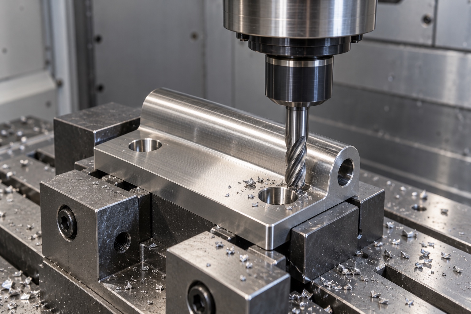
Plan machining around the functional axis
The route should preserve the relationship between the bore and mounting geometry through all required setups. Stable support matters when material is removed around the barrel or mounting base. Review tool access before production, especially where an internal transition affects the pin or retention detail. Chips beneath setup contacts can introduce error even when the program is correct. Intermediate checks help confirm a route but do not replace inspection of the finished part. Do not prescribe one drilling, boring or reaming method universally; select the process for the actual material, geometry and approved drawing requirements.
Control entrances, exits and final treatment
Burrs at bore entrances, mounting holes or underside exits can alter seating and assembly access. Specify edge conditions that preserve functional geometry rather than applying unrestricted rounding. If passivation or another final process is required, agree documentation and final-state inspection needs before treatment. A polished surface is not proof of cleanliness, corrosion resistance or suitable hinge behavior. Keep markings away from functional contacts unless approved. Cleaning should follow the purchased scope and should not conceal a damaged bore or reference surface by presenting the component in an attractive package or a lightly fitted demonstration assembly.
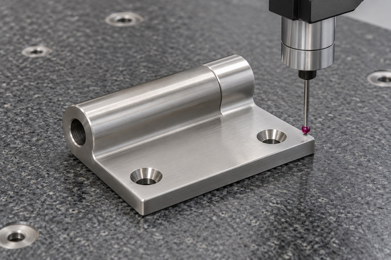
Measure the drawing-defined relationships
Map each requirement to a method that can reach and evaluate the actual feature. Depending on the drawing, relevant evidence may include bore size and form, axis relationships and mounting-hole geometry. Record the support and reference condition. A mating gauge or pin check should have an identified acceptance meaning; passing an undocumented sample fit is not equivalent to verifying every drawing requirement. Resolve inaccessible measurement questions during planning. If an installed-condition check is required, define it separately rather than allowing a strongly clamped setup to hide the free-condition geometry the drawing expects the supplier to report.
Define movement trials and endurance separately
A controlled assembly trial can check insertion, agreed movement and clearance with identified components. Load capacity, wear, endurance and enclosure safety need separate evaluation under approved conditions and criteria. They are not established by moving a door once for a photograph. Record the block revision, pin, mating elements and installation arrangement used in any demonstration. Changes to the door, pin, material or mounting support can require renewed review. A component dimensional report should not be presented as a completed safety or life-cycle qualification of the medical equipment service door or its access-control arrangement.
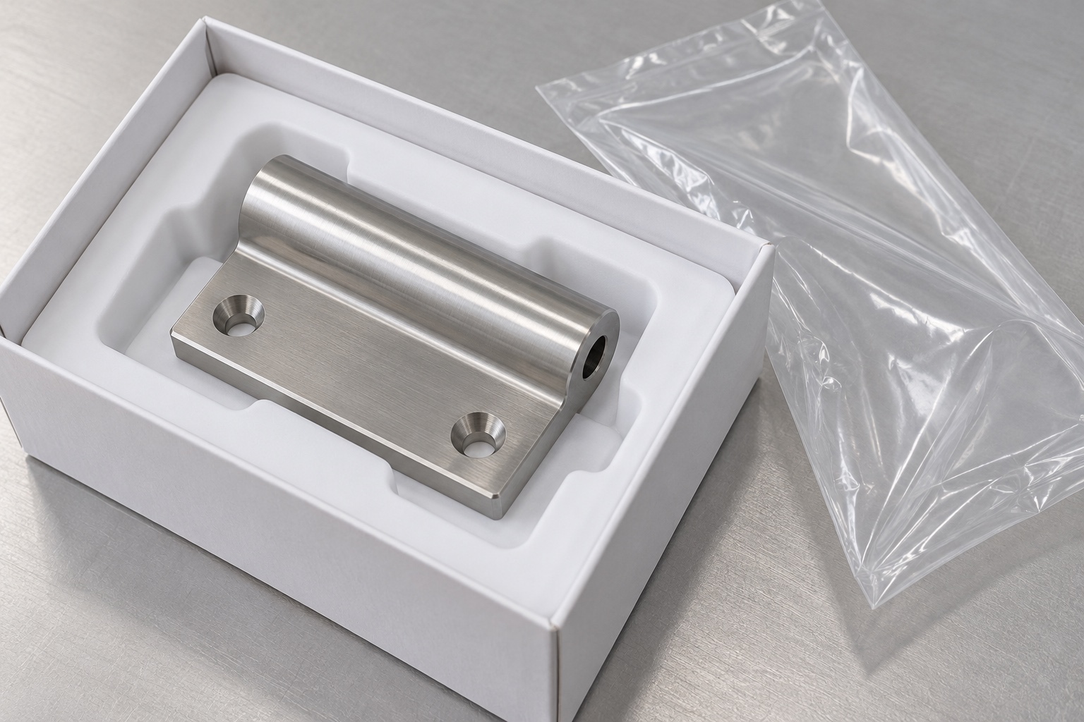
Protect bores and mounting contacts
Packaging should prevent bore edges and mounting faces from striking neighboring metal parts. Separate blocks and any supplied pins, maintaining their identity and approved configuration. Protective supports should avoid leaving residue in the bore or on reference surfaces. Ordinary transport protection is not sterile packaging or proof of a quantified cleanliness level. If a specific cleanliness criterion is purchased, state its verification method. Preserve material lot and drawing revision with the shipment. Receiving staff should be able to distinguish an accepted block from a visually similar trial part before it is installed in a controlled equipment assembly.
Request a component with explicit evidence
A complete inquiry includes the approved drawing, model, pin and retention information, mounting references, movement envelope, material condition and inspection deliverables. State whether an assembly trial is purchased and keep endurance, load and safety evaluation separate unless their scope and responsibility are explicitly agreed. Retain authorized changes and approved revisions for repeat manufacture. Review altered pins, doors, installation or materials before transferring earlier conclusions. This turns a hinge block into a traceable manufactured interface without asking a CNC supplier to invent the reliability, access-protection or medical-device qualification requirements of the complete equipment system.
Manufacturer background reference: www.elesa-ganter.com.
FAQ
Is a machined hinge block a safety interlock?
No. Mechanical movement support and safety functions are different design responsibilities. The complete equipment must define any required lock, stop or interlock and its evaluation; hinge appearance or dimensional acceptance does not establish those functions.
Does pin-bore diameter alone define the hinge interface?
No. Mating pin, retention, contact geometry, mounting references and movement requirements also matter. Use approved interface documents rather than a universal clearance or an unrecorded sample that happens to move by hand.
Can a catalog hinge rating be applied to a custom block?
Not automatically. Catalog claims apply to particular products and conditions. A custom block, pin, door or installation requires review and the appropriate evaluation within its own complete approved configuration.
Why inspect the bore relative to mounting references?
That relationship controls how the component locates the hinge axis when installed. An acceptable isolated diameter does not establish axis alignment or the position of a door supported by multiple mounted components.
Does a movement demonstration prove endurance?
No. It proves only the explicitly agreed checks under the recorded configuration. Wear, load capacity, endurance and enclosure safety require separate procedures, conditions and acceptance criteria defined by the responsible equipment program.
What changes require review before a repeat order?
Review altered bore or pin geometry, retention, materials, door configuration, mounting support and final process. Retain approved revisions and evidence rather than transferring earlier assembly or qualification conclusions to a different configuration.

tanghangyun@oemach.com