
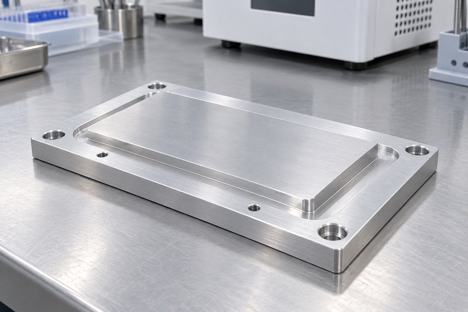
Define the base within the thermal assembly
A machined heat-sink base provides a mechanical and thermal interface within medical equipment electronics. It may connect a heat-generating module to another cooling component, but the plate alone does not establish a cooling rating. The equipment team must define the actual heat path, mounting arrangement and operating conditions. This article addresses the solid machined base, not a qualified complete thermal system or a fluid-cooled component. Begin by distinguishing the module contact face, equipment mounting surfaces and interfaces to any separate fins, enclosure or thermal interface material before specifying manufacturing and inspection requirements.

Obtain the approved contact arrangement
A nominal module footprint is not enough to define the contact region. Obtain the approved component envelope, mounting pattern, permitted contact zones and surrounding clearances. The design may use one broad contact island or several separately controlled surfaces. Identify which regions actually carry contact and which provide clearance. A visually similar module can have a different underside or fastening arrangement, so a sample should not replace controlled documents. The manufacturing drawing must relate the selected contact geometry to the installation references rather than asking the supplier to infer thermal requirements from a photograph.
Separate flatness from surface texture
Flatness describes geometric form, while surface texture describes smaller-scale surface characteristics. They should not be treated as interchangeable requirements. A shiny machined face can still have form error, and a dimensional report does not automatically characterize texture. Define the requirements that the approved thermal design actually needs and identify suitable inspection methods. The referenced thermal manufacturer describes several heat-sink constructions, reinforcing that one manufacturing route does not cover every assembly. Do not copy a catalog thermal-performance statement or an unrelated surface requirement into a custom plate specification without engineering review.
Include interface material and fastening inputs
The equipment designer must specify whether a thermal interface material is used and how the assembly is fastened. Its thickness, installation condition and approved application process are not decisions that a machining supplier should invent. Fastener locations and local support can affect the assembled contact condition, even when the free plate meets its drawing. Review screw-head access and the full mating arrangement before manufacture. This article provides no universal tightening torque, contact pressure or interface thickness. Those values require the actual component specifications and the responsible team's thermal and mechanical evaluation of the complete configuration.
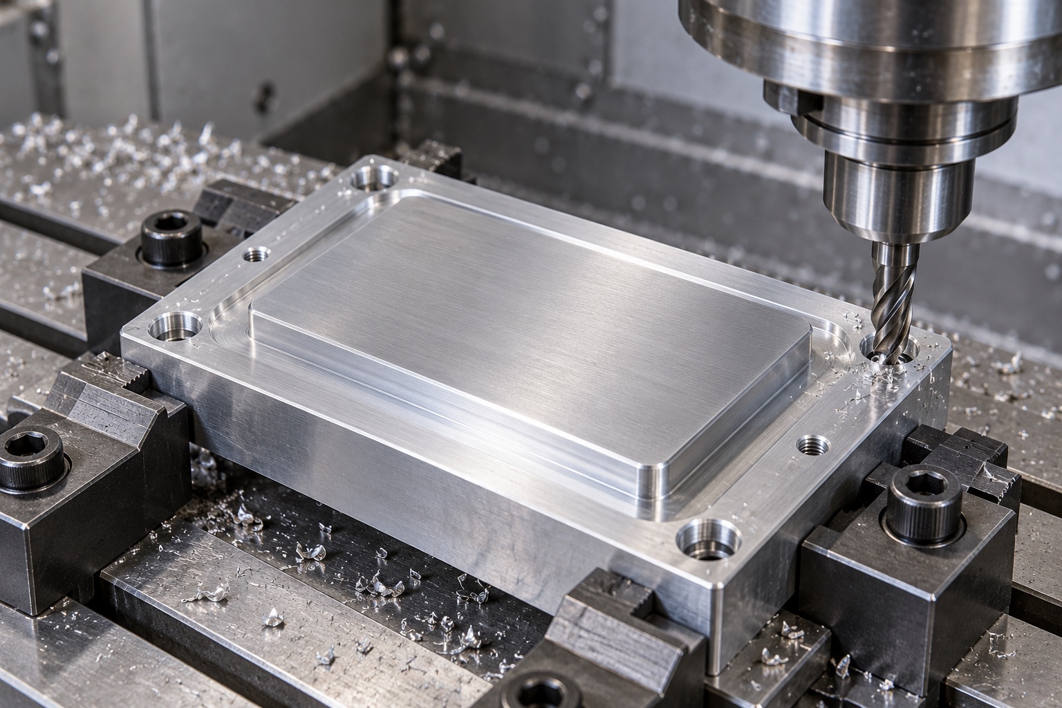
Define accessible geometric references
The contact face must be related to a clear set of mounting references. An outside edge convenient for machining may not establish the actual position of the heat source after assembly. Identify how contact height, mounting holes and any locating features relate to the approved reference scheme. State whether a requirement applies in the free condition or under a defined mounting arrangement. Those are different acceptance conditions. Measurement fixtures should not force a distorted plate flat and then present that result as evidence of free-condition geometry, especially where a thin section can respond to clamp force.
Plan supported material removal
A stepped plate can change stiffness as material is removed. Plan roughing, finishing and setup transfers so the workpiece remains supported without being forced into an artificial shape. Chips beneath contact locations can undermine a correct program by changing the setup reference. Intermediate checks can help confirm the route, but final acceptance must address the finished part in the drawing-defined condition. The appropriate cutting conditions depend on raw material, tools, equipment and geometry. There is no responsible universal feed, speed or clamping force for every medical equipment heat-sink base from a general article.
Keep holes and transitions functional
Mounting holes, screw threads and steps should be reviewed together with tool access and mating clearances. Internal radii must be compatible with the approved module envelope. Burrs around a hole or raised contact island can change seating or interfere with assembly, even if the main face appears smooth. Specify the required edge condition instead of applying unrestricted polishing. Examine underside exits and transitions as deliberately as visible top features. Any relief needed for manufacturing should be approved before production rather than hidden in a workshop modification that later becomes difficult to inspect or reproduce.
Plan final treatment before dimensional approval
If anodizing or another final process is specified, identify masking requirements and the state in which critical dimensions are accepted. A finish selected for appearance should not silently cover a surface intended to have a particular contact condition. Electrical insulation, corrosion behavior and thermal performance remain application questions that require appropriate evidence. Do not assume an aluminum alloy or coating is compatible with every cleaning chemical. Keep treatment documentation associated with the lot and review changes to the finishing process against the accepted configuration rather than considering them automatically cosmetic or irrelevant to the interface.
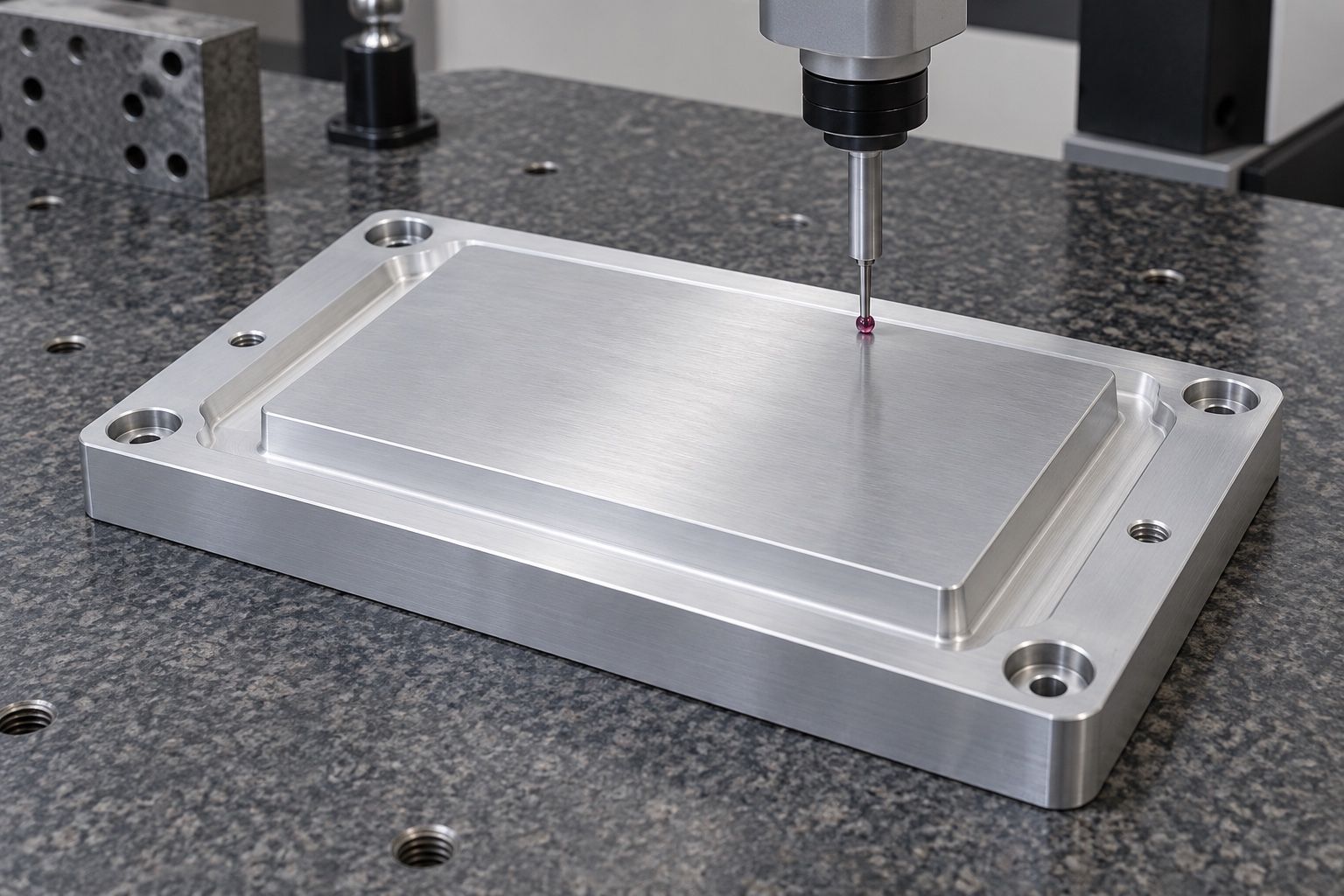
Inspect the relationships that control assembly
A feature-linked inspection plan should address the contact geometry, mounting references and specified hole relationships. Suitable methods depend on accessibility and the exact requirement; a single instrument is not automatically adequate for every feature. Record the support condition and any required environmental controls during measurement. An outside length and width report is not a complete verification of the thermal mounting interface. Where surface texture is specified, document its agreed evaluation separately. If a feature cannot be measured reliably using the proposed route, resolve that issue before production rather than substituting an easier but unrelated dimension.
Define assembly checks and thermal tests separately
An agreed assembly trial can check module seating, fastener access and clearance using identified mating components. It does not establish operating temperature, thermal resistance or safe equipment performance without a separately defined evaluation. The responsible program must specify heat input, surrounding conditions, interface materials, installation and acceptance criteria. Record which plate revision and assembly configuration are used. A changed module, fan arrangement or enclosure can require review even if the metal plate is unchanged. Do not describe a photograph of a mounted module as a thermal qualification or transfer results from an unrecorded prototype.
Protect the contact surface in transport
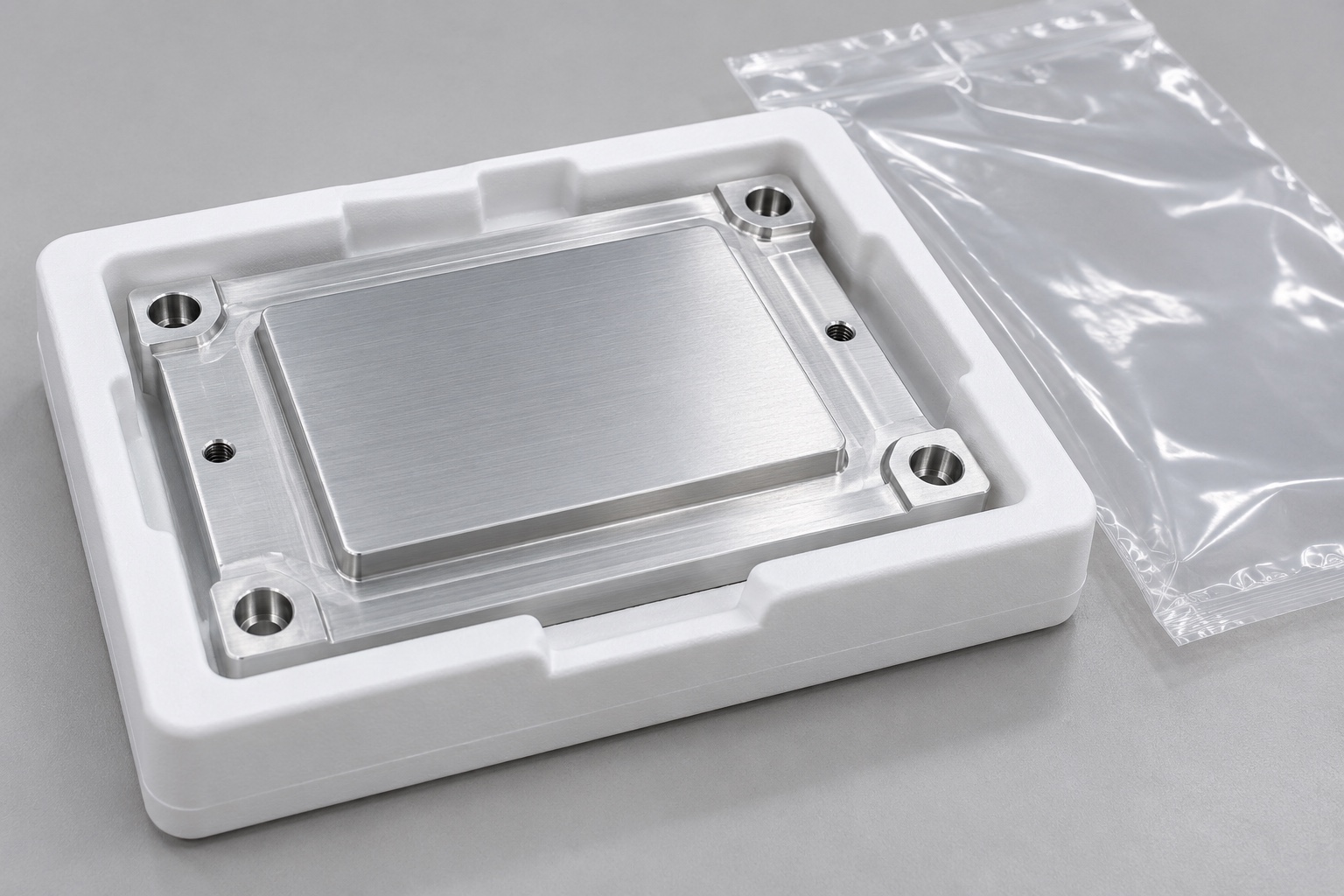
Package the base so its functional faces cannot rub against neighboring parts or collect uncontrolled residue. Protective materials should not introduce fibers or adhesive to contact regions under the agreed cleanliness scope. Separate plates and support them without bending thin areas. Ordinary component protection is not sterile packaging, and a clean appearance is not evidence of a quantified cleanliness level. Where a specific cleanliness requirement is purchased, define its verification method explicitly. Maintain revision and material identity with the shipment so receiving staff can distinguish the accepted configuration from a visually similar trial or substitute part.
Make repeat purchases configuration-specific
A complete inquiry includes the approved drawing, model, contact arrangement, mounting hardware, material condition, final process and inspection deliverables. State whether an assembly trial is included and keep thermal qualification separate unless its scope is explicitly agreed. Preserve authorized prototype changes and the approved revision for repeat production. Review altered interface materials, modules, installation or cooling arrangements before reusing earlier conclusions. This creates a testable purchase boundary: a traceable machined base with defined geometry and evidence, without unsupported promises about the temperature, reliability or medical suitability of the complete equipment in which it is installed.
Manufacturer background reference: www.eaton.com.
FAQ
Does the machined base establish a cooling rating?
No. Cooling depends on the complete thermal path, heat input, interface materials, installation and surrounding conditions. A dimensional report verifies only its agreed component scope and is not a complete thermal qualification.
Are flatness and surface texture the same requirement?
No. They describe different aspects of a surface and may need different measurement methods. Define both only where required by the approved design, and do not substitute a shiny appearance for either form or texture evidence.
Who specifies the interface material and tightening conditions?
The responsible equipment design team must approve those inputs for the actual assembly. A machining supplier should not invent universal torque, contact pressure or interface thickness values for an unspecified thermal system.
Why distinguish free and mounted measurement conditions?
Fastening can change the shape of a thin plate. State which condition each requirement applies to, and do not force the part flat during inspection while claiming to report its free-condition geometry.
Can a coating be added without another review?
Not automatically. Masking, final dimensions and functional contact conditions may be affected. Review the treatment against the approved configuration and required application evidence before changing the production specification.
What should accompany a repeat order?
Retain the approved revision, material, finish, contact arrangement, mounting information and inspection plan. Review changes to modules, interface materials or installation before transferring earlier assembly or thermal conclusions to the new configuration.

tanghangyun@oemach.com