
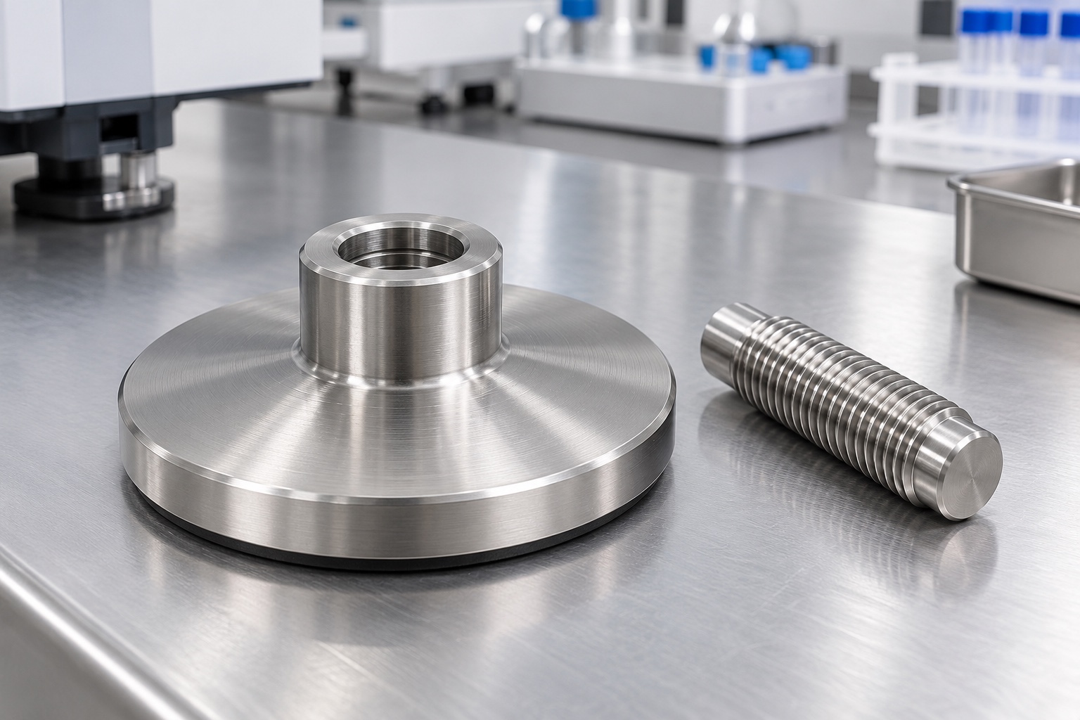
Define the pad within the complete support
A leveling-foot pad is one component in the support arrangement of a laboratory instrument. It may receive an adjustment stem and provide a defined contact interface to a bench, floor or separately specified insert. The pad alone is not a rated support system. The equipment design must establish how loads pass through the complete assembly and how adjustment is secured. This article addresses a machined equipment component, not patient support or medical-device safety certification. Begin by distinguishing the pad, stem, locking hardware, contact insert and mounting structure before specifying manufacturing requirements.

Do not transfer catalog load values
Commercial leveling elements are supplied with particular geometry, materials and stated operating conditions. The referenced manufacturer explicitly distinguishes conditions affecting the load capacity of its own product. Those values cannot be assigned to a custom 316L pad or a different stem arrangement. The responsible equipment team must define its own analysis and testing scope. A machining supplier can provide material and dimensional evidence, but cannot derive an allowable load from the pad's diameter or appearance alone. Side loads, installation conditions and the rest of the assembly require application-specific engineering review.
Identify the real base-contact geometry
A circular outside diameter does not describe how the support contacts its mounting surface. The design may require a full face, an annular region or a separate approved contact insert. Identify the actual contact areas and keep decorative reliefs separate from functional geometry. A pad can look flat while touching at an unintended edge. The drawing should specify relevant flatness or other requirements in a clear measurement condition. Do not assume that machining a bright surface establishes adequate friction, vibration isolation or protection of the bench; those depend on the approved assembly and environment.
Define the stem interface completely
The central recess may locate, support or retain a stem depending on the design. Obtain the approved mating geometry and identify which surfaces transfer force. A simple blind cylindrical recess is not automatically a spherical joint or a threaded connection. If threads or retaining elements are required, specify their geometry and acceptance requirements explicitly. Review access for assembly and removal as well as the final installed position. A sample stem can help confirm agreed checks but should not replace controlled interface documentation, particularly when contact shape and retention details are not visible after assembly.
Separate pad machining from adjustment design
Adjustment range, locking method and permitted stem position belong to the complete support design. They should not be inferred from the pad drawing. The equipment owner must establish how the support is installed and which configuration is evaluated. A change to stem engagement or a contact insert can alter the relevant assembly conditions even if the metal pad is unchanged. Keep those design responsibilities explicit in the purchase scope. An attractive turned component and a smooth manual adjustment demonstration are not evidence of long-term stability, adequate load capacity or suitability for every laboratory installation.
Select the stainless material and condition
316L may be a specified input for a proposed pad, but it does not establish a universal corrosion guarantee or allowable load. Obtain the required material condition and traceability documents, and review the actual cleaning and environmental exposure. The grade of a mating stem or insert may be different and should be specified separately. A visually similar stainless blank is not automatically equivalent. If a supplier proposes a different material or raw material form for production efficiency, approval should precede manufacture and the resulting configuration should remain identifiable in the order documentation.
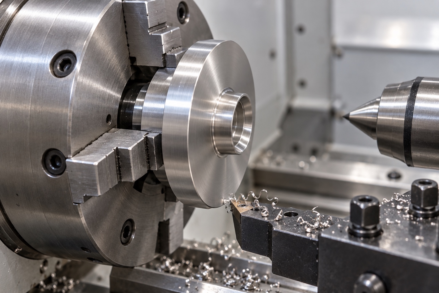
Plan turning around functional relationships
The turning route should relate the base-contact geometry and stem-interface axis to the drawing-defined references. Workholding must support the part without hiding distortion or damaging finished contact regions. Review how a second setup preserves those relationships when the opposite face is completed. Chips at the chuck or setup contacts can undermine a correct program. Internal tool access must suit the approved recess, including any specified bottom transition. Do not convert a convenient drilling result into an assumed functional seat without checking what the drawing actually requires at the bottom and side walls.
Treat edges and finishes as controlled features
Burrs at the recess entrance and outer rim can affect assembly or contact. Define their required condition rather than applying unrestricted polishing. If passivation, a surface texture requirement or another final process is specified, include its records and final-state inspection needs in the purchase documents. A polished appearance does not establish cleanliness or corrosion performance. Keep identification away from defined contact regions unless approved. Any separate contact insert must have its own specification and retention requirements; the metal pad should not acquire an improvised insert simply to make a demonstration seem stable or non-slip.
Inspect the drawing-defined support geometry
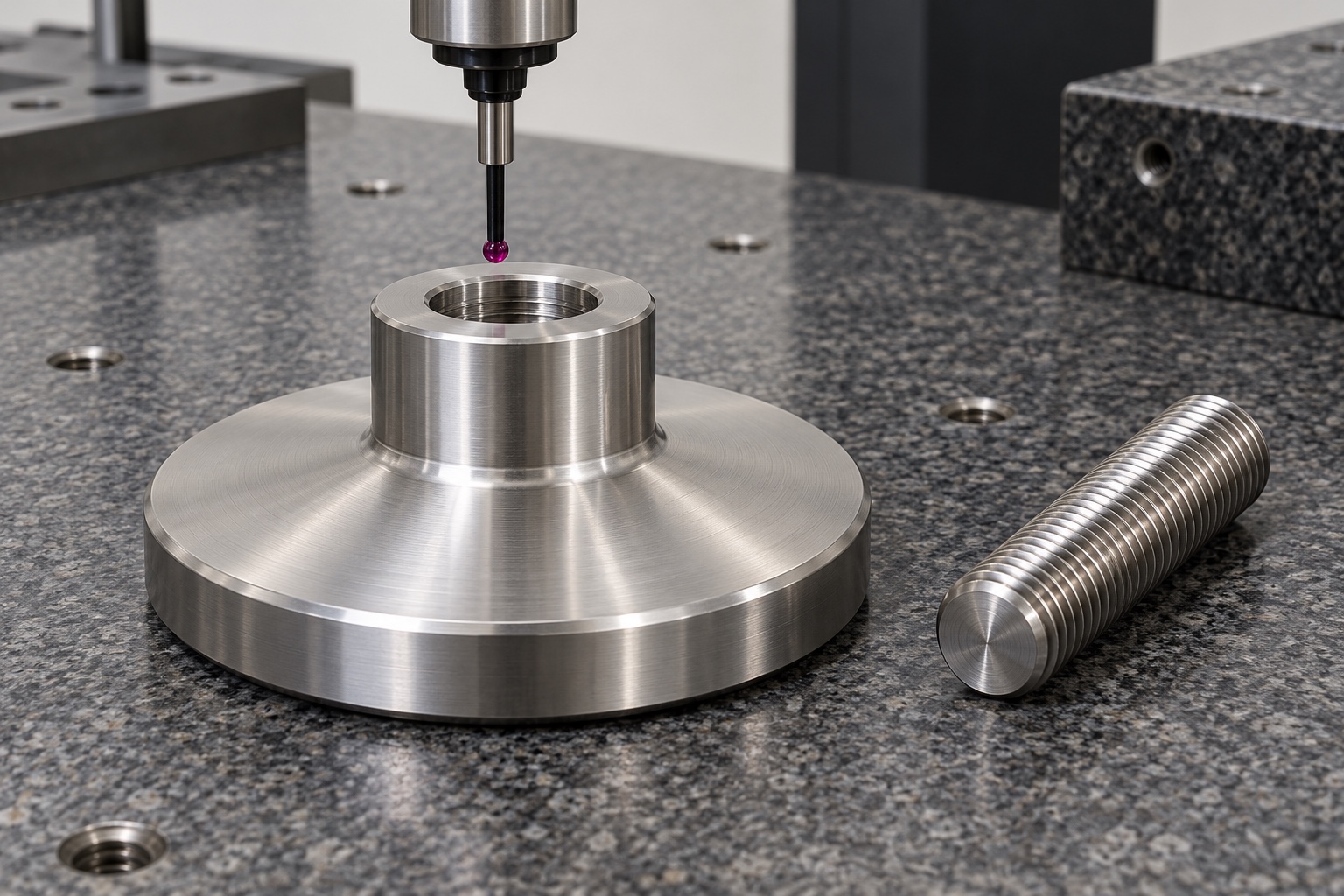
Map each requirement to a measurement method that can reach the actual feature. Relevant checks may include contact-face geometry, recess dimensions and the relationship of the stem interface to the base. Record support conditions and distinguish free-condition inspection from any separately defined loaded or installed check. A single outside-diameter measurement does not establish the support interface. If a gauge or mating sample is used, identify it and state what passing the check means. A feature-numbered report gives the equipment team evidence that can be evaluated against the approved drawing.
Agree assembly and load evaluations separately
A defined assembly trial can check stem insertion and agreed clearances using identified components. Load capacity, stability, endurance and vibration behavior need separate analysis or tests with approved conditions and acceptance criteria. These cannot be proved by placing a weight on one unrecorded sample for a photograph. The responsible equipment program should identify the mounting structure, contact surface, stem position and hardware used in its evaluation. If any of those change, review whether prior results remain applicable. A machining supplier's dimensional report must not be presented as a completed equipment safety qualification.
Protect contact surfaces and material identity
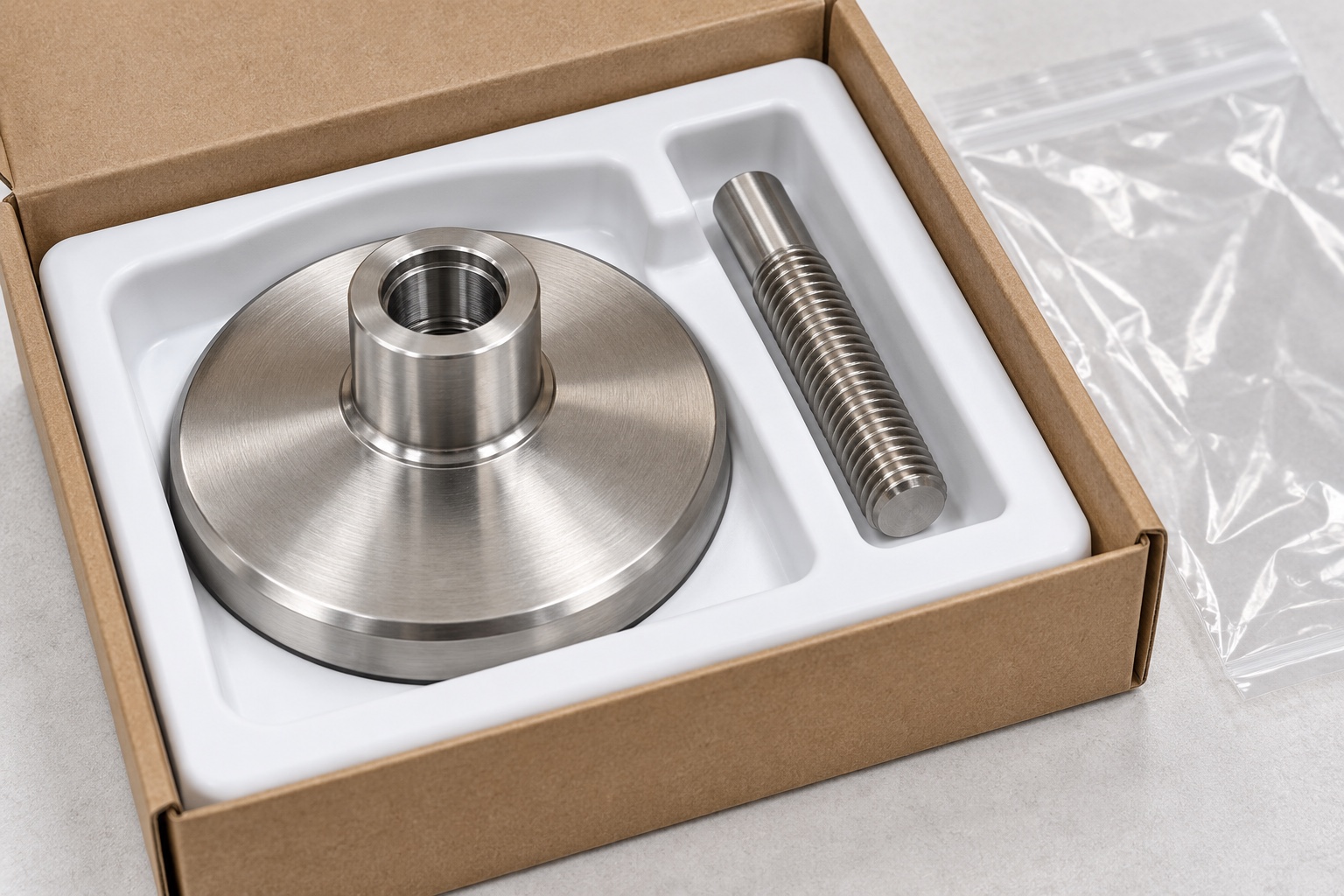
Packaging should prevent contact faces and recess edges from striking neighboring parts. Separate metal components and any approved inserts so their identities are not confused during receiving. State the cleaning scope accurately and do not imply sterile supply from ordinary protective bags. If a cleanliness requirement is purchased, define its verification independently from visual inspection. Keep the drawing revision, lot and material documents linked to the shipment. The recipient should be able to distinguish an accepted pad from a visually similar trial component and install it only within the equipment program's approved support arrangement.
Request a controlled component, not an assumed rating
A useful inquiry includes the pad drawing, model, mating stem geometry, contact arrangement, material condition, final process and inspection deliverables. State whether an assembly trial is required and keep load or stability qualification outside that scope unless separately agreed. Preserve authorized changes and the approved configuration for repeat production. Review altered stems, inserts, installation surfaces or support structures before reusing prior conclusions. This creates a clear manufacturing boundary: a traceable machined pad with specified geometry, without unsupported claims about the complete laboratory instrument's load rating, vibration performance or clinical suitability.
Manufacturer background reference: www.elesa-ganter.com.
FAQ
Does a 316L pad have an automatic load rating?
No. Allowable load depends on the complete support design, materials, contact conditions and installation. It requires the responsible team's defined engineering evaluation rather than an inference from alloy or outside diameter.
Can a catalog leveling-foot rating be reused?
Not automatically. Catalog values apply to a specific product and stated conditions. A different pad, stem, contact insert or installation must be evaluated within its own approved assembly configuration.
Is a blind recess necessarily a spherical joint?
No. The approved drawing must define the actual stem interface, contact geometry and any retention features. A similar-looking recess does not establish a particular joint function or accepted mating arrangement.
What does the dimensional inspection need to cover?
It should cover drawing-defined contact geometry, recess features and their relationships to the references. Record the measurement condition, and distinguish those results from separate loaded or installed assembly checks.
Can an assembly trial prove stability and endurance?
Only the explicitly defined checks can be claimed. A simple insertion or clearance demonstration does not establish load capacity, long-term stability, vibration behavior or equipment safety without separately approved evaluation.
Which changes affect repeat-order review?
Review altered pad geometry, stem, insert, material, finishing process and installation arrangement. Preserve approved revisions and evidence so conclusions are not silently transferred to a different support configuration.

tanghangyun@oemach.com