
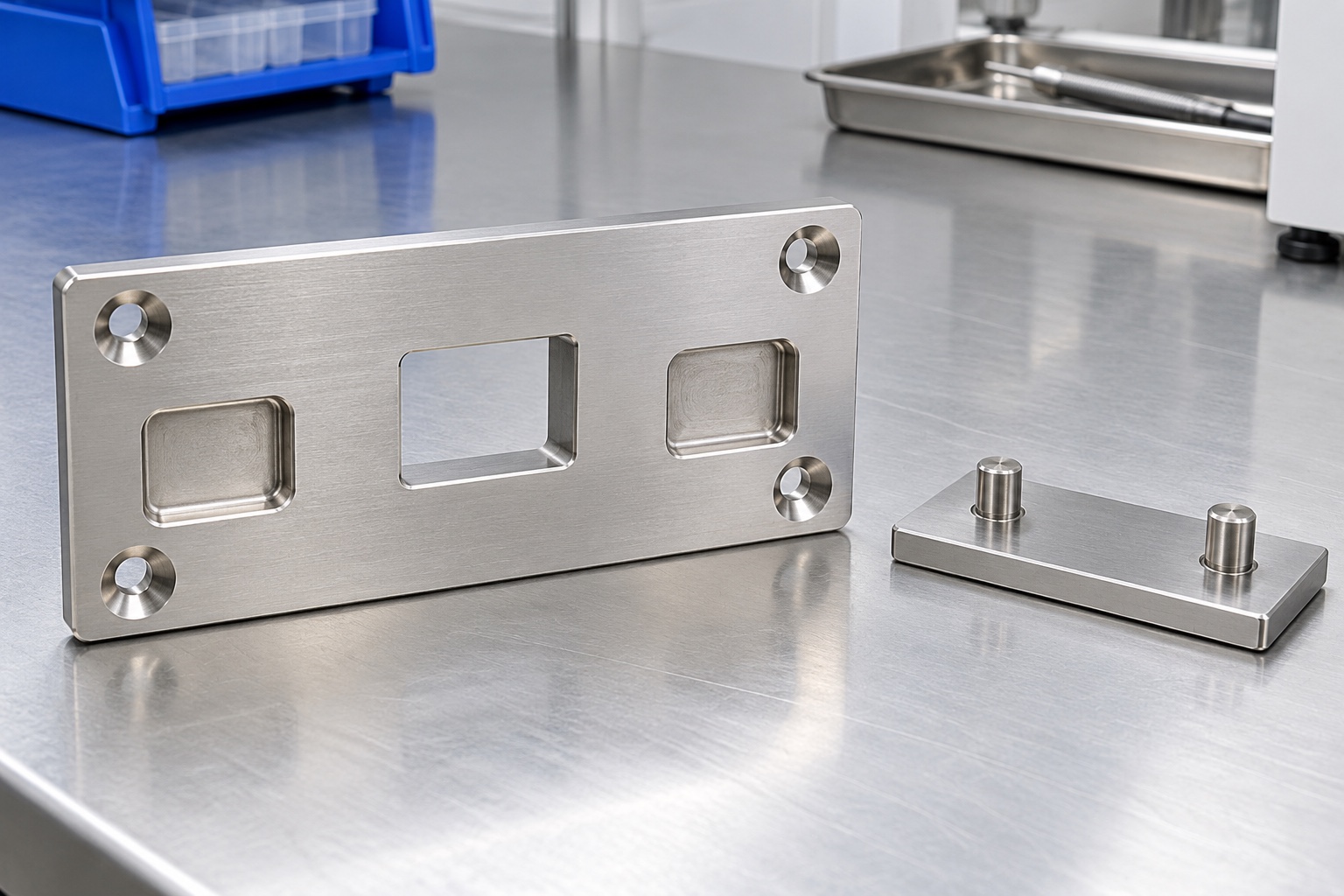
Define the mechanical interface
A docking plate can connect a removable equipment module to a cart, support or service fixture. Its machined features may establish position, provide fastener access and leave room for a retention mechanism. These functions must be defined for the actual equipment program. A generic metal plate is not a load-rated docking system or proof of safe medical use. Manufacturer information about quick-access hardware illustrates the variety of available arrangements, but it does not approve a custom receiver. Start with the complete interface and assigned responsibilities before selecting material or manufacturing tolerances.

Separate location from retention
Locating surfaces establish how the module sits, while a latch or other retention feature prevents unwanted separation under the approved design conditions. A fastener may perform one role, both roles or neither, depending on the assembly. Identify the intended contact sequence and load path on the interface documents. If a latch is forced to correct a misaligned locating feature, the assembly may conceal an underlying geometric problem. The machining supplier needs the specified relationships, not an invitation to determine safe retention from appearance. Equipment-level safety and load evaluation remain separate tasks.
Review the complete insertion envelope
An interface that fits in its final position can still interfere during insertion or removal. Review the motion of mating pins, latch elements, fastener heads and surrounding covers throughout the approved docking path. Include access for service tools and the intended removal procedure. The relevant clearance is not necessarily the gap visible in a static model. Identify any allowed contact and areas that must remain free. If the equipment designer has not established the motion envelope, resolve that input before a supplier commits to a receiver geometry or an assembly demonstration.
Use references that match installation
The mounting face, locating recesses or other specified features should establish a coherent geometric reference scheme. It should connect the machining drawing to how the receiver is installed and inspected. An outside edge chosen only for convenience may not control the actual assembled position. Identify whether requirements apply before mounting, under a defined installation condition or both. Measurement fixtures must not force a distorted plate into an apparently acceptable state. A feature-linked inspection report should state its reference and support condition so that results can be interpreted by the assembly team.
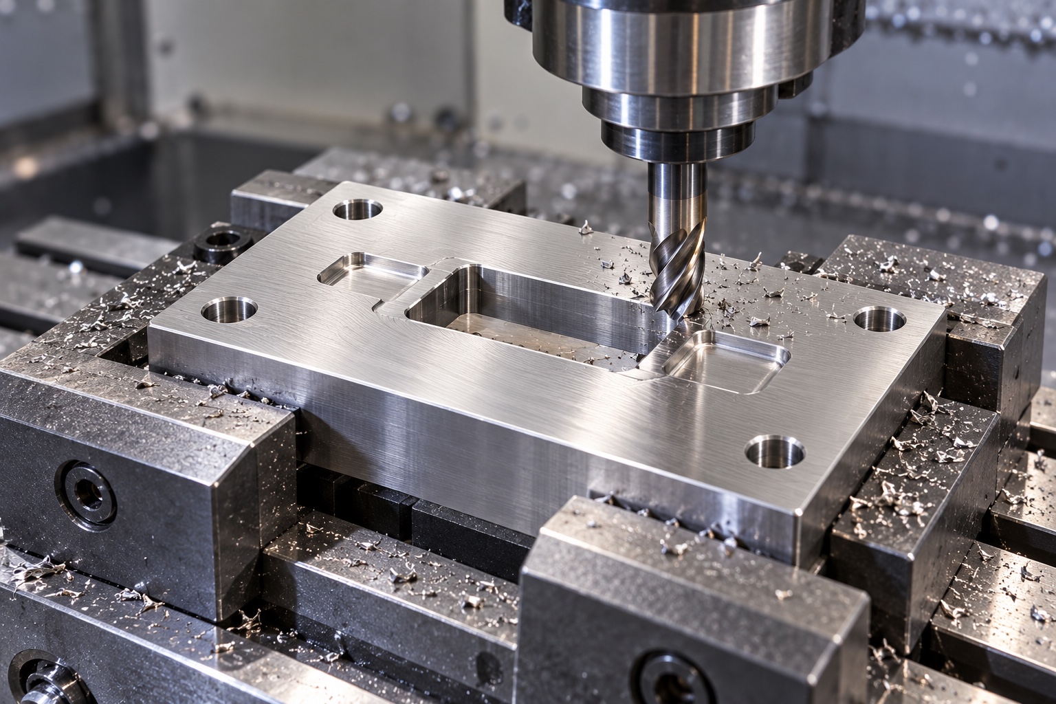
Specify the actual retention hardware
A latch window must suit the approved hardware geometry and movement, not merely a rough rectangular opening in a model. Obtain the relevant interface dimensions and keep the supplier's hardware specifications separate from the custom plate requirements. Do not transfer catalog holding-force claims to a different receiver, mating part or installation. Screw-head shape, engagement and access also require review. If the design uses a purchased latch, its integration must follow the equipment team's approved documents. CNC capability alone does not establish that the complete docking arrangement meets a safety or reliability objective.
Choose material for the environment
316L stainless steel may be considered where the approved design calls for it, but alloy selection must address the actual equipment environment, cleaning procedure and mating materials. The designation does not provide a universal corrosion guarantee or establish an allowable load. Specify raw material condition and any required documentation. Consider surface treatment and contact behavior as part of the engineering review rather than assuming that all silver-colored parts are interchangeable. If a different material is proposed for cost or machining reasons, its acceptance requires a controlled design decision, not an undocumented purchasing substitution.
Plan machining around functional surfaces
The route should preserve support while recesses, windows and mounting features are produced. Cutting a large opening can reduce local stiffness, so workholding and operation sequence deserve attention even for a seemingly simple plate. Relate finishing operations to the functional reference scheme and inspect after releasing clamps where required. Inside corner radii must be compatible with the approved mating geometry and available tool access. Do not leave the assembly team to discover that a cutter radius prevents a latch from reaching its intended position after the part has already been delivered.
Control edges and final treatment
Burrs near locating recesses, latch windows and mounting holes can alter seating or obstruct a moving element. Specify edge conditions for the relevant surfaces instead of applying unrestricted rounding everywhere. If passivation or another final treatment is required, define the process and final inspection condition in the purchase documents. A treatment record is not a replacement for dimensional acceptance, nor does a polished appearance prove suitable contact behavior. Inspect hidden exits and underside features as deliberately as visible faces. Keep any identification marking away from functional contact areas unless explicitly approved.
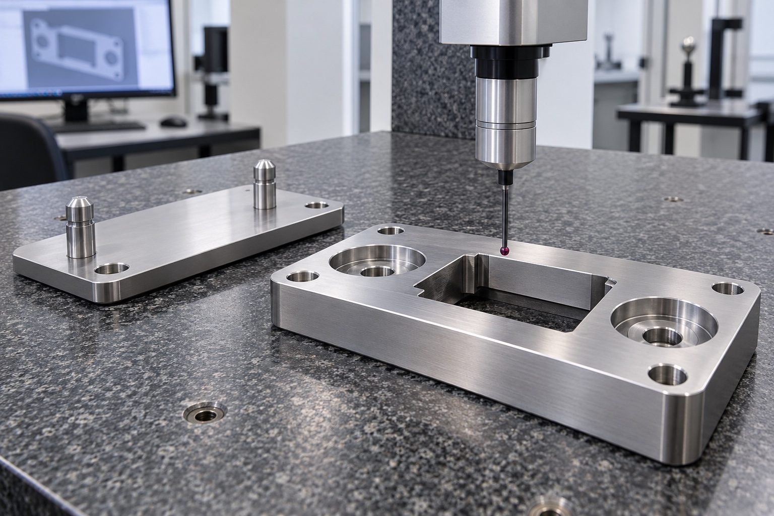
Inspect relationships rather than isolated sizes
A receiver can have individually correct recess diameters and still position the module incorrectly if their relationship to the mounting plane is wrong. Map the drawing requirements to suitable measurement methods and retain feature identifiers in the report. Check the latch clearance geometry in the state required by the drawing. Where a mating gauge is used, define its identity, condition and acceptance meaning. Passing an undocumented sample fit is not equivalent to verifying every geometric requirement. Resolve inaccessible measurements during planning rather than accepting a convenient dimension that does not control the interface.
Define assembly and load tests separately
A controlled assembly trial can evaluate agreed insertion, seating and removal checks with identified mating hardware. It does not establish safe load capacity, vibration resistance or service life without a separately defined validation program. The equipment owner must provide the applicable conditions, procedures and acceptance criteria. Record the plate revision, hardware configuration and mounting arrangement for any trial. If a design change follows an interference finding, reassess the affected checks. Do not extend a result from one configuration to a different latch, fastener or support structure without engineering review.
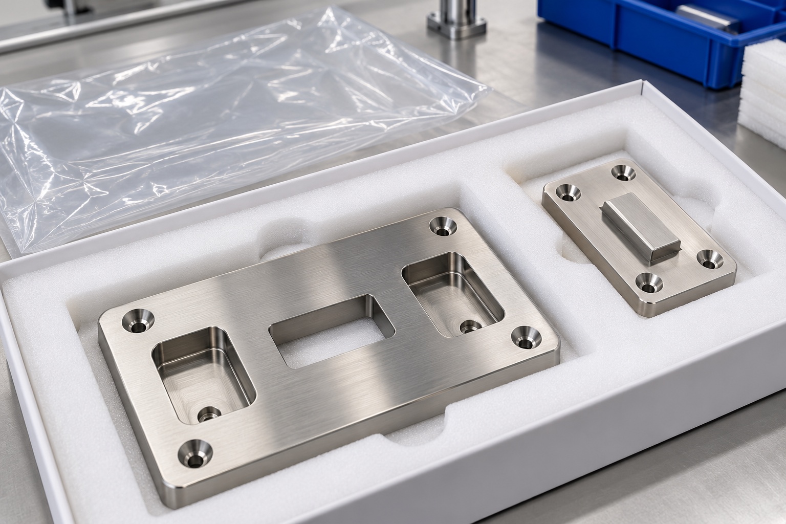
Protect locating surfaces during shipment
Separate mating and receiver parts so that transport cannot repeatedly strike the locating surfaces. Use protective supports that do not bend a thin region or deposit residues in recesses and windows. Cleaning and packaging requirements should correspond to the agreed equipment assembly process. Protective packaging is not automatically sterile packaging, and stainless construction does not make a component ready for any clinical environment. Keep material identity, drawing revision and inspection records linked to the delivered lot. This allows the recipient to distinguish the accepted component configuration from a visually similar but undocumented replacement.
Prepare a complete manufacturing inquiry
A useful inquiry includes the controlled model and drawing, mounting arrangement, mating geometry, approved retention hardware, material condition, final treatment and required inspection evidence. State whether an assembly trial is part of the order, and keep that service separate from load or device-level validation. For repeat production, retain approved revisions and review any change to the latch, support structure or installation method. A well-defined purchase request turns a docking receiver into a testable mechanical interface without asking the machining supplier to invent the performance requirements of the complete medical equipment system.
Manufacturer background reference: southco.com.
FAQ
Does the receiver plate alone determine safe holding capacity?
No. The complete load path includes mating components, hardware, mounting and support structure. Safe capacity requires the equipment team's defined analysis and testing; a component drawing or fit check is not sufficient.
Why separate locating features from the latch?
They can have different roles. The interface documents should identify how the module is positioned and retained so that the latch does not unintentionally compensate for a misaligned or poorly supported locating arrangement.
Can catalog latch ratings be applied to a custom plate?
Not automatically. Catalog statements relate to specified hardware and conditions. A custom receiver, mating geometry or installation must be reviewed within the complete approved equipment configuration before performance claims are made.
Is 316L suitable for every cleaning process?
No universal compatibility is assumed. The actual cleaning chemicals, exposure conditions, surface treatment and equipment requirements must be reviewed. Alloy identity alone does not establish suitability for every medical environment.
What does a docking assembly trial verify?
Only the agreed checks, such as insertion, seating, clearance and removal using identified components. Load capacity, endurance and equipment safety require separately defined procedures and acceptance criteria.
What should a repeat-order package retain?
Keep the approved plate revision, mating-interface documents, hardware configuration, material and treatment requirements, inspection plan and authorized changes. Review altered installation conditions before repeating the previous production specification.

tanghangyun@oemach.com