
Understand what the ring does
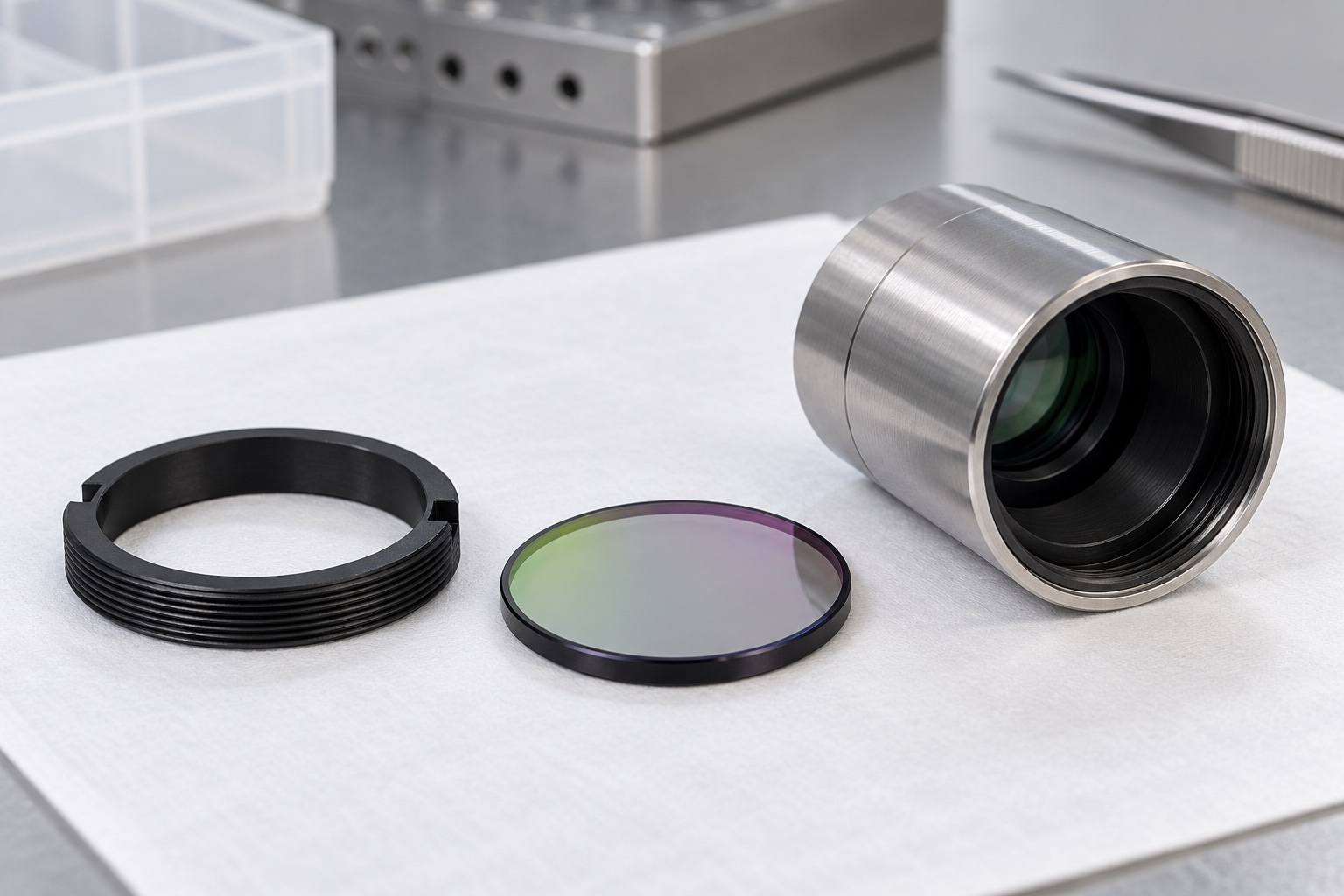
A diagnostic photometer can use a mechanical ring to retain a filter within a defined optical assembly. The ring may provide an axial contact surface, an aperture and a threaded connection to the surrounding tube. It is not the optical filter and does not by itself establish analytical accuracy, spectral transmission or stray-light performance. Begin by identifying the intended mechanical function and the acceptable contact region on the mating optic. A generic retaining-ring photograph cannot establish compatibility. The released interface must describe how the actual component is located, retained, installed and removed.

Define aperture and contact as different features
The clear opening and the axial contact land serve different purposes. Opening the aperture without considering the contact land can leave insufficient support, while increasing the land can obstruct an intended optical path. Record the required diameter, axial position and edge condition of each feature. Identify whether contact is direct or through another specified component. Do not assume that a visible circular face is an approved bearing surface. The ring drawing and assembly definition should agree about which side faces the optic and how the contact region relates to the thread and tool-access features.
Specify the actual thread
Write the thread form, pitch, size and acceptance requirements explicitly. A nominal diameter or an informal reference to a lens-tube family is not a complete manufacturing specification. Include lead-in geometry, usable engagement length and the relationship between the thread and contact face. Review the approved mating tube or gauge if a fit check is requested. A ring that can be forced into one sample has not demonstrated a controlled thread fit. Conversely, a dimensional thread check does not establish the complete assembled axial position if shoulder geometry or another part of the stack is wrong.
Choose material using the real environment
Black POM is one possible material for an equipment-side ring, but a color description is not a material specification. Confirm polymer grade, stock form and any required certification. Review temperature, cleaning exposure, loading and the period during which the ring retains the optic. The actual instrument may require another polymer, metal or surface condition. Do not infer biological suitability, low fluorescence or optical cleanliness from the material name. Any particulate, outgassing or optical-background requirement needs the designer's defined assessment and evidence rather than a general statement that a dark material is appropriate for optics.
Support a thin ring without changing its acceptance state
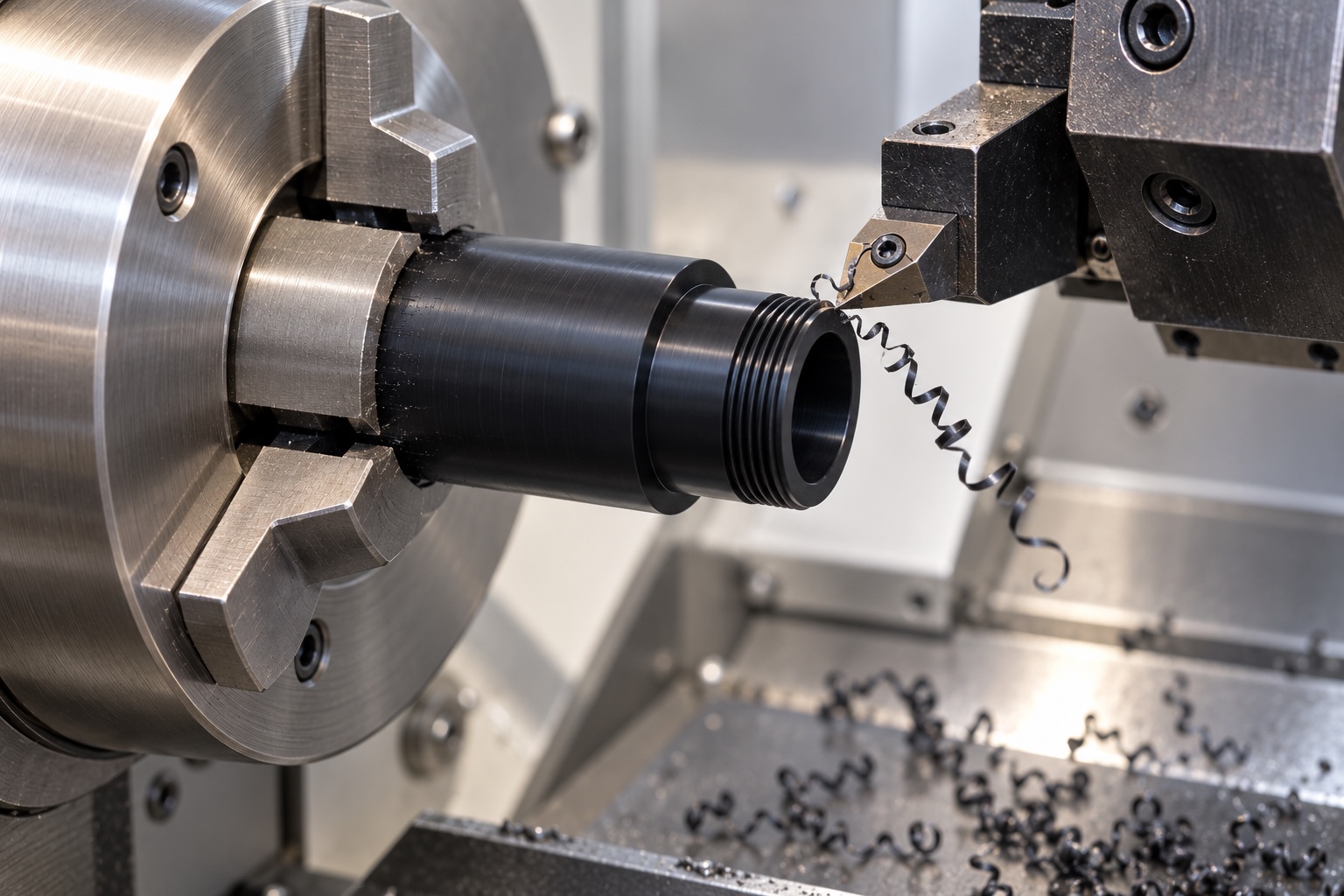
A narrow annular part can distort while it is held. Review how the chuck, collet, soft jaws or a supported mandrel contacts the blank and the finished surfaces. The suitable strategy depends on the ring's geometry and the operations still required. A size measured while the ring is compressed may differ after release. Define when the component is allowed to stabilize and in what condition it is inspected. Where a second operation is required, preserve the intended reference instead of using an unfinished or easily distorted edge as an uncontrolled locator.
Plan turning and slotting together
A possible sequence establishes the main diameters and contact face by turning, then completes tool-access slots using a controlled secondary setup. Another geometry may favor a different order. Review remaining wall thickness and whether slotting changes the stiffness of a previously finished ring. Tool entry, burr direction and access to the inner edge deserve attention. If the spanner feature has a specific engagement depth or width, state it clearly. A slot that looks acceptable in a photograph may still prevent installation or allow the tool to contact a nearby optical surface.
Remove strings and burrs without rounding the land
Polymer machining can leave fine strings or attached edges that need a defined removal and inspection process. The requirement is not simply to make the ring feel smooth. Excessive edge finishing can remove the intended contact width, open an aperture or change a thread entry. Identify which edges permit a break and which require controlled geometry. Review the tool slots after the final relevant operation. Cleaning can remove loose debris but does not confirm that an attached string is gone. Use handling and inspection methods that do not scratch the land or introduce new contamination.
Treat temperature as an inspection condition
Record the material and the conditions relevant to dimensional comparison. A polymer ring measured immediately after cutting may not be in the same condition as its mating tube during assembly. The drawing and inspection plan determine how this is addressed; a universal waiting period or compensation is not justified for every grade and geometry. Distinguish free-state dimensions from an assembled observation under load. Avoid explaining an inconsistent result solely by temperature before checking the method, fixture contact and actual part identity. A repeatable procedure is more useful than an undocumented adjustment to make one sample fit.

Check the relationships that affect assembly
The inspection plan can include the aperture, contact land, overall width, thread characteristics, tool slots and the specified geometric relationships. Select methods that resolve the features without loading the part excessively. Record the drawing revision and any approved mating reference. Do not treat a single outside diameter measurement as proof that a thin ring is circular or that its axial face is correctly related to the thread. Where the specified relationship cannot be measured with the proposed fixture, resolve the method before the first article rather than after the lot has been made.
Keep tightening requirements with the assembly design
Thorlabs' optomechanical guidance illustrates that retaining arrangements and tightening practices are specific to the assembly. That is useful context, not a torque specification for a custom polymer ring. The equipment team should define the installation tool, engagement, contact arrangement and acceptable tightening procedure. A ring that passes dimensional inspection does not prove that an optic is unstressed or that an instrument meets its optical requirements. Keep component measurements, assembly observations and optical performance testing separate, with clear references connecting the records. Do not use catalog installation values as generic shop acceptance limits.
Protect the optical-mechanical interface
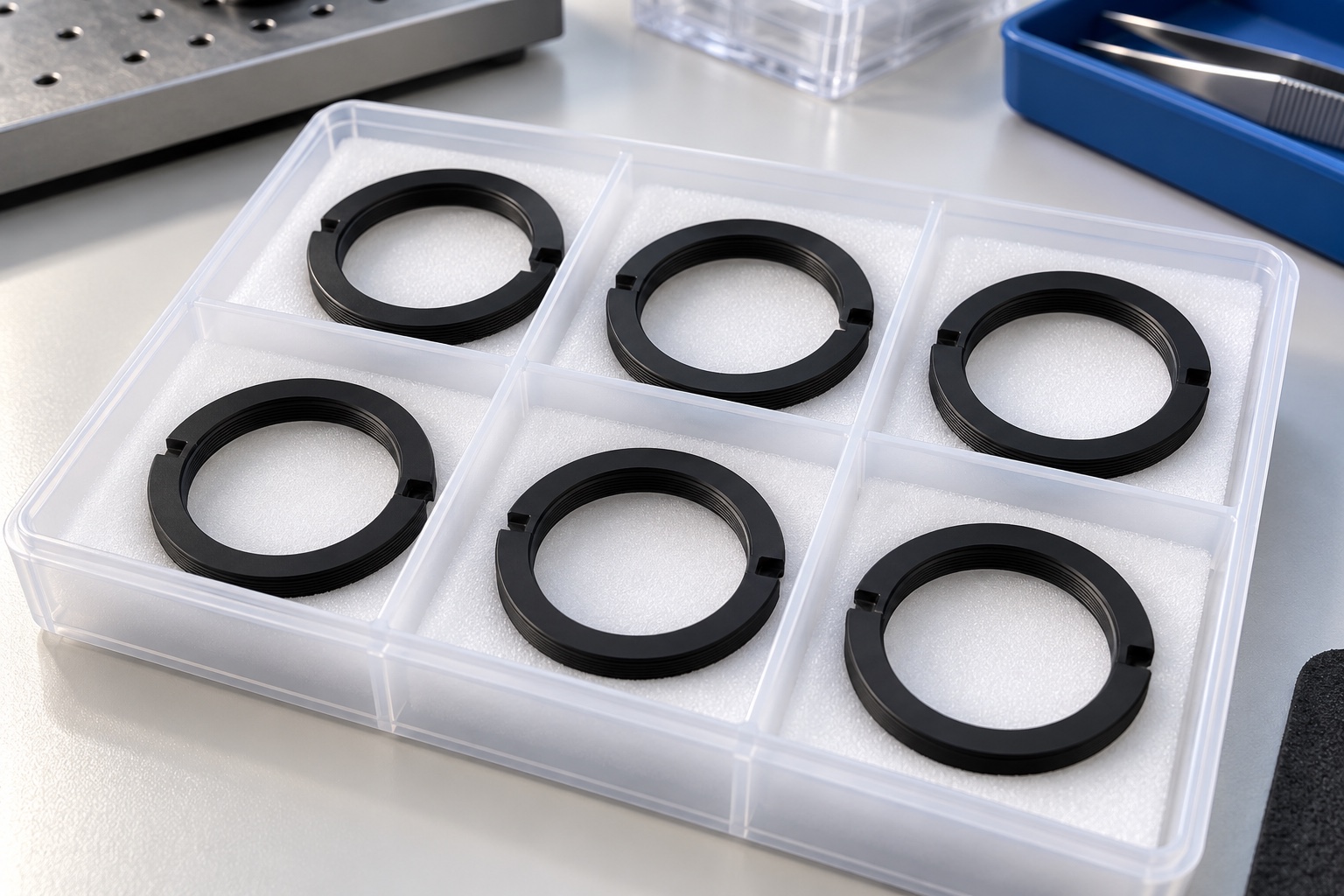
Use a cleaning route compatible with the selected material and the agreed residue requirements. Keep labels and abrasive contact away from the land and thread. Package rings separately or with suitable separation so their tool slots and edges cannot rub the next component. The packaging method should not shed particles onto the contact region. Record the part, revision and lot without implying sterile delivery or a special cleanliness class unless those requirements were ordered and verified. Appearance alone cannot establish a residue limit, and a black surface can make some contamination harder to notice.
Request the information needed for repeat production
A complete RFQ includes the drawing and model, polymer grade, prototype and repeat quantities, mating-thread definition, contact requirements, edge notes and inspection evidence. Include the approved tube, optic surrogate or gauge if an assembly trial is part of the order. State what the trial proves and who approves it. Preserve accepted first-article records and review changes to stock, clamping, tools or edge finishing. If the filter stack changes, revisit the ring interface rather than relying on the same nominal outer diameter. Repeatability begins with a defined assembly, not an informal instruction to make the ring fit.
Manufacturer background reference: www.thorlabs.com.
FAQ
What determines the clear aperture?
The released optical and mechanical interface determines the required opening and its location. The aperture and contact land should be specified separately so machining does not improve one feature by unintentionally compromising the other.
Can a similar-looking thread be substituted?
No substitution should be assumed from diameter or appearance. Confirm form, pitch, engagement and acceptance requirements with the approved mating interface. Any proposed alternative needs an engineering disposition before it is treated as equivalent.
Why inspect the ring after release?
A thin ring can be distorted by its workholding or measurement fixture. The free-state condition and any defined assembled checks should be documented so an apparently correct clamped measurement is not confused with the delivered component.
Does black POM guarantee low stray light?
No. Color and polymer identity do not establish optical performance. Geometry, the complete assembly and material-specific requirements need their own review and evidence. Any optical-background or cleanliness limit must be explicitly defined.
Who sets installation torque?
The assembly designer should define the installation arrangement and acceptable procedure using the actual components. A catalog value for another ring or a successful dimensional inspection does not provide a universal tightening limit for a custom part.
Which files and samples support approval?
Provide the controlled ring drawing and model, material grade, mating-thread information, contact and edge requirements, quantities and inspection plan. Approved mating tubes or surrogates can support a separately agreed trial but do not replace missing drawing requirements.

tanghangyun@oemach.com