
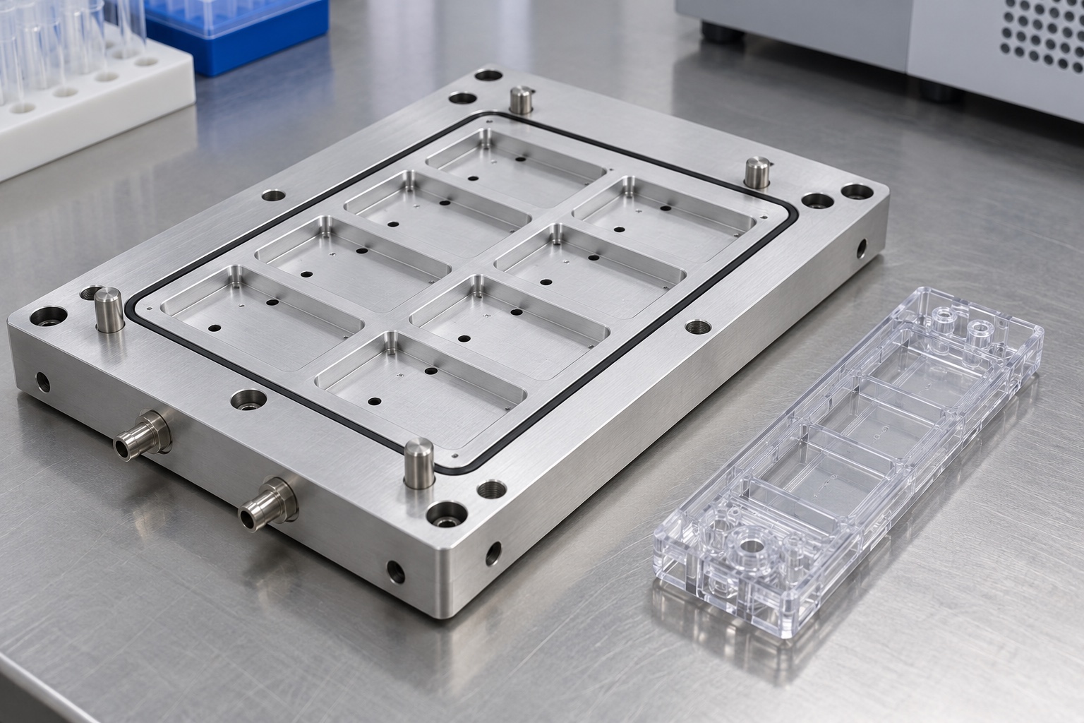
A representative fixture component
This case describes a proposed manufacturing route for a 6061 aluminum vacuum platen used on the equipment side of a diagnostic cartridge inspection station. It is a representative engineering example, not a named customer order or a report of delivered performance. The concept has a rectangular mounting body, raised cartridge support regions, locating holes, shallow seal grooves and a connection to a vacuum passage. The device team defines the actual cartridge interface and operating conditions. The machining supplier's responsibility is to reproduce the released component geometry and provide the agreed evidence for that component.

Review the controlled interface package
Begin with a matching drawing and three-dimensional model. Identify the installation face, support height, locating holes, seal path and vacuum connection. Mark which regions contact the cartridge and which provide clearance. Ask for the approved gasket definition rather than inferring it from a rendering. When a sample is supplied, record its identity and purpose: a reference for an assembly trial is not an automatic replacement for missing dimensions. Any conflicting groove depth, hole position or surface requirement should receive a documented disposition before the route and quotation are accepted.
Keep stock condition and lot identity visible
The example uses 6061 aluminum in the condition specified by the eventual order. Confirm the requested material condition, blank form and certificate requirements before purchasing stock. Leave sufficient allowance for the mounting and working faces while considering the material removed by pockets and passages. Maintain lot identification after cutting the blank so the finished plate can be connected to its records. Neither the alloy name nor its appearance proves suitability for every medical environment. Cleaning chemistry, contact classification and any required special documentation remain separate requirements that the equipment designer must define.
Plan roughing without forcing the final shape
A possible route roughs the main outline and reliefs while retaining supported reference surfaces for subsequent operations. Review whether material should be removed from both sides before final finishing. The objective is not to prescribe one universal stress-management sequence but to identify where the proposed plate can move when material or fixture loads are released. Avoid placing the strongest clamping force on a narrow sealing land. Check the released part at a useful intermediate point and record any approved process change. A part held flat by the machine fixture has not yet demonstrated its delivered condition.
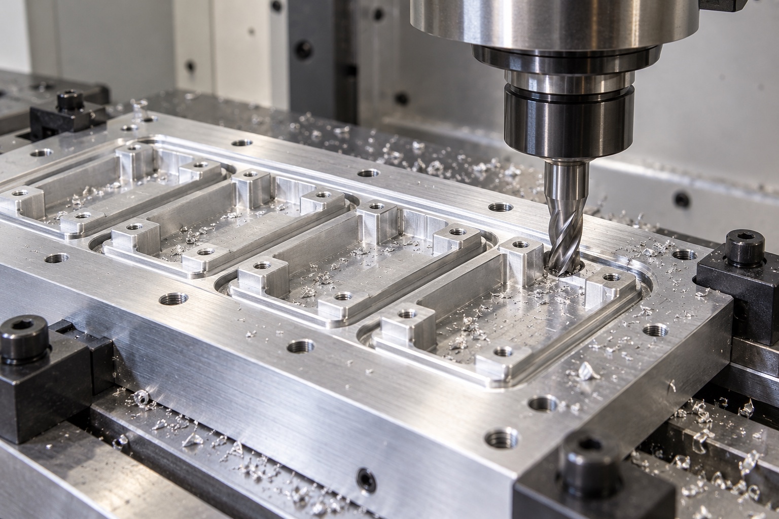
Transfer references to the support geometry
Finish the mounting interface and establish the references needed to locate the cartridge supports, dowel holes and groove features. When the part changes setups, identify what locates it and what merely holds it down. Inspect the transferred relationship instead of assuming that a repeatable machine coordinate proves the relationship on the physical plate. Support pads may require their own collective geometry requirement rather than a general finish note for the whole top surface. The drawing determines that distinction. Keep tool access and probe access in mind so the planned evidence can actually be obtained.
Mill the gasket path and connection details
The shallow seal groove is machined using tools and entries suited to its width, depth and corner geometry. Before selecting the cutter, compare its attainable corner form with the released model. Review nearby mounting holes and locating features for unexpected intersections. The vacuum port may be drilled and connected through an accessible route, with any plug or fitting defined in the order. Record the supplied configuration. A drawing that requires a sharp internal corner or an uninspectable intersection may need clarification; the shop should not silently alter either feature to make its preferred tooling fit.
Complete controlled edge finishing
Plan a deliberate edge process after the relevant cutting operations. The groove lips, port entries and passage intersections can have different acceptance requirements from the external perimeter. Remove loose metal without enlarging a groove, rounding a cartridge locator or reducing a support pad. Inspect the result using a method appropriate to the feature and its access. Polishing the visible face does not demonstrate the condition of an internal passage. If a finishing operation exposes a previously hidden edge, include that edge in the review rather than relying on the earlier deburring record.
Review the finished surface condition
An order may specify anodizing, a different finish or no additional treatment. This case does not assume that one choice is universally required. Where treatment is ordered, confirm masking, appearance limits and the dimensions that apply afterward. Recheck support regions, locating interfaces and seal grooves if their acceptance can be affected. Maintain the link between the part lot and treatment documentation. A finish certificate describes the ordered process; it does not independently demonstrate laboratory chemical compatibility, a sterile condition or the function of an assembled vacuum station.
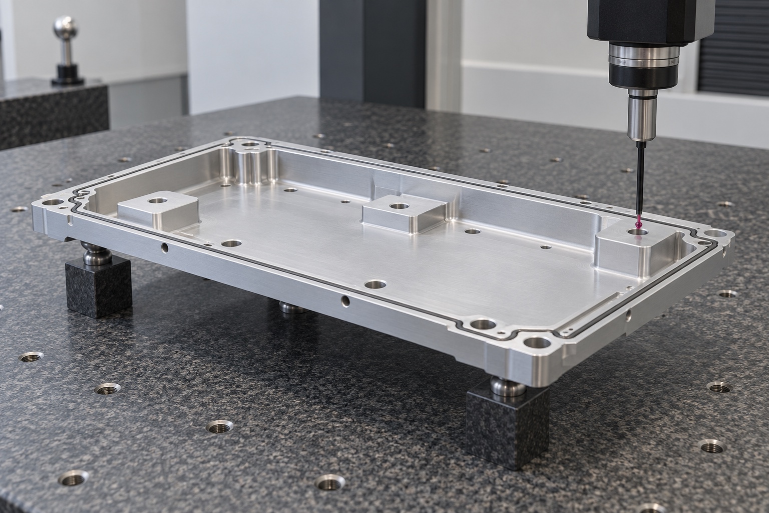
Prepare the first-article report
The proposed report identifies the drawing revision and material lot, then records the agreed mounting features, support geometry, locating holes, groove characteristics and port configuration. State how the plate was supported during measurement. Where released-state behavior matters, do not substitute readings taken under heavy clamping. Distinguish directly measured results from calculations or assembly observations. Numbered drawing characteristics make it easier to resolve a deviation or compare repeat orders. The example supplies no invented measurement table: actual accepted values must come from the manufactured part, the approved method and the released drawing.
Quote the assembled trial as defined work
If requested, a separate fixture trial can use the approved cartridge or surrogate, gasket, fittings and vacuum circuit. Agree the observation, equipment and acceptance rule before manufacturing. A holding demonstration, leakage measurement and repeated loading study are not the same service. Identify who provides consumables and who approves the trial record. This representative case claims no measured leakage, holding force or inspection-station repeatability. If a trial fails, document its configuration before deciding whether to modify a machined dimension, a seal, a cartridge reference or another element outside the supplied plate.
Clean and package without damaging the working face
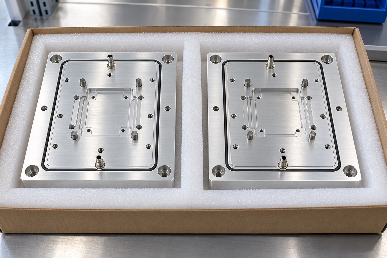
After the agreed cleaning and drying route, protect the cartridge support regions and seal grooves from contact with adjacent parts. Keep adhesive labels on the packaging, not on the functional face. Any port cover should be compatible with the passage and should not shed debris into it. Use individual separation and identify part number, revision, quantity and lot. The delivery record should describe the actual cleaning and inspection performed. A protective bag or tray is not a sterile barrier, and a clean-looking surface is not proof of a specified particle or residue limit.
Release a repeatable order package
A repeat build should preserve the accepted drawing, model, material condition, finish, inspection plan and any authorized deviations. Review changes to gasket references, cartridge samples, clamping methods or the treatment route for their effect on previously accepted features. Keep first-article approval separate from approval of the complete station. A useful inquiry also states prototype and repeat quantities, packaging, evidence requirements and responsibility for assembly testing. This example promises no universal tolerance capability, price or lead time. Those commitments require review of the actual controlled geometry and the work needed to verify it.
Manufacturer background reference: www.schmalz.com.
FAQ
Is this a delivered customer project?
No. It is a representative manufacturing example without a named customer, shipment or measured vacuum result. A real order needs its own released geometry, agreed acceptance criteria, inspection records and delivery evidence.
Why is aluminum used in the example?
6061 aluminum is the specified concept material, not a recommendation for every diagnostic fixture. The designer must confirm material condition, stiffness, finish, cleaning compatibility and the requirements of the actual equipment environment.
What should be checked after unclamping?
Check the drawing features whose acceptance depends on the released condition, including the specified support geometry and mounting relationships. A surface forced against a fixture during machining may not represent the delivered plate.
Can anodizing change what must be inspected?
Yes. The order should identify masking and finished-condition dimensions. Review locating interfaces, support regions and groove features after treatment where relevant, and retain the ordered process documentation with the part lot.
Can a vacuum trial be included?
It can be separately agreed using the defined cartridge, gasket, circuit, procedure and acceptance conditions. This example does not establish those values or claim an achieved result for an unbuilt fixture.
What defines the repeat-order configuration?
Use the accepted drawing and model revisions, material and finish, first-article disposition, inspection plan, approved mating references and packaging requirements. Review a change to the cartridge or gasket rather than assuming it cannot affect the fixture.

tanghangyun@oemach.com