
CNC Machining Medical Imaging Collimator Mount Plates: Flatness, Detector Datums and Clean Assembly
Why a mount plate affects imaging repeatability
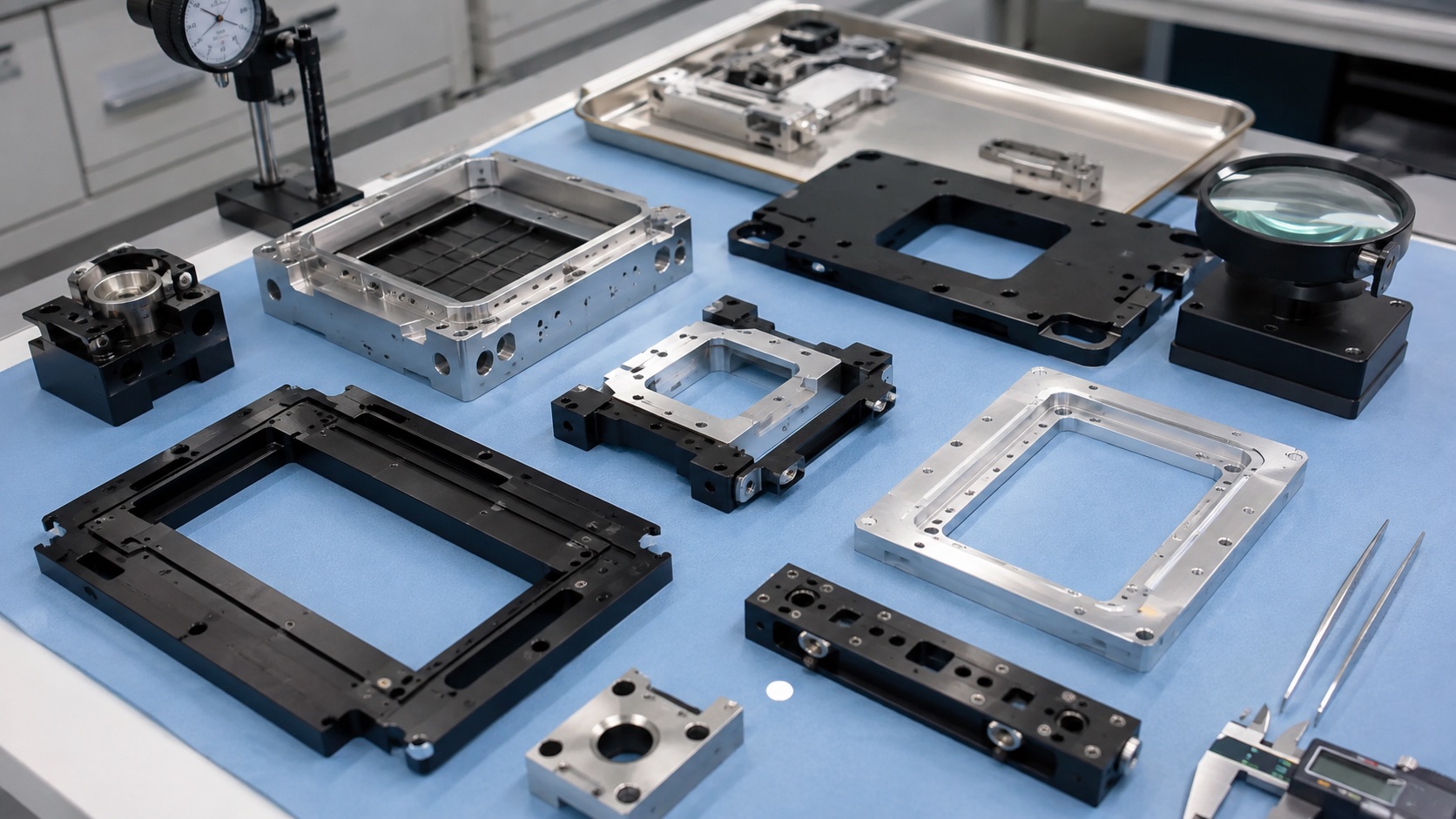
A medical imaging collimator mount plate or detector support part is not just a flat bracket. It fixes the relationship between the source path, collimator, detector carrier and shielding hardware. Small shifts in flatness, perpendicularity or hole pattern position can make later alignment work slower and less repeatable. The machining plan should therefore treat the part as an optical or imaging datum structure, even when the part is made from ordinary aluminum or stainless steel stock.

Start from the datum chain
Before quoting, review how the plate locates to the frame and how the collimator, sensor carrier, shield or calibration target locates to the plate. A drawing should identify primary mounting faces, dowel holes, slot functions, threaded inserts and any adjustment features. If a long slot is only for coarse assembly clearance, it should not be inspected like a precision datum. If a dowel hole defines the detector coordinate system, it deserves tighter process control and first-article measurement.
Material and stress control
Aluminum alloys are common because they machine well and keep moving mass low. Stainless steel may be selected for stiffness, wear or cleaning resistance. The material choice should consider plate size, pocket depth, tapped holes, anodizing or passivation, shielding interfaces and the temperature range of the equipment. For broad plates, stress relief, balanced roughing and free-state inspection matter because clamping can hide bow during machining.
Flatness and support condition
Flatness values are meaningful only when the support condition is defined. A large plate may meet a flatness requirement on a granite table but behave differently after being bolted to an equipment frame. The drawing should clarify whether flatness is checked free-state, restrained at mounting holes or after a defined torque pattern. This prevents disagreement between machine shop data and assembly results.
Hole patterns, slots and inserts
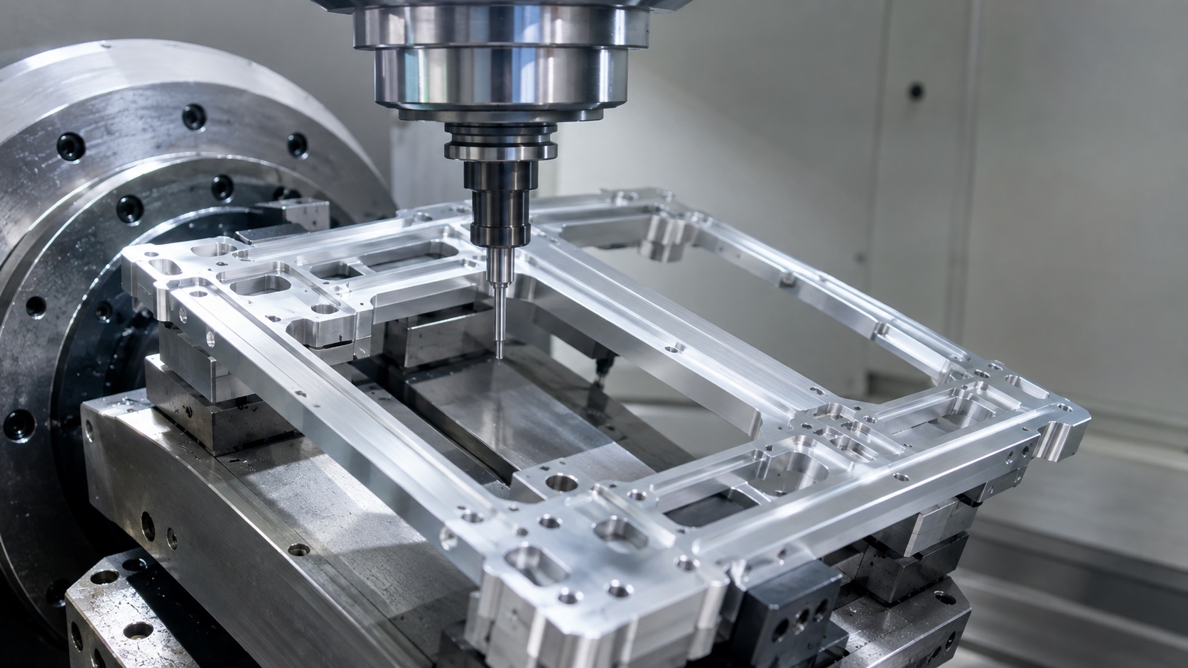
Medical imaging plates often combine dowel holes, counterbores, threaded holes, cable clearance and adjustment slots. These features should be grouped by function. Locating holes need stable coordinates; service slots need burr-free edges; threaded holes need engagement and gauge checks. If helicoils or threaded inserts are used, the installation requirement and inspection method should be specified before production.
Machining sequence and fixturing
A robust sequence roughs large pockets or lightening features, allows the plate to relax, then finishes mounting faces, dowel holes and precision patterns from controlled references. Vacuum fixtures, soft jaws or supported plates can reduce distortion, but the final check after unclamping is essential. Tool paths should avoid creating raised lips around slots or counterbores that could interfere with shields or detector carriers.
Surface treatment and masking
Anodizing, conversion coating, passivation or black finish may be used for corrosion protection, reflectivity control or cosmetic consistency. Masking may be needed on ground contact areas, tight dowel bores or threaded features. Finish thickness can influence dowel fits and insert installation, so the drawing should state whether dimensions apply before or after finish.
Inspection and documentation
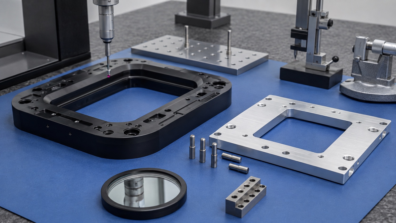
A first-article plan can include CMM results for datum holes and mounting patterns, flatness reports, thread gauges, surface finish review, coating records, photos of masked or contact areas and material certificates. If the part supports calibration or detector alignment, the inspection report should use the same datum logic as the equipment assembly process.
Cleaning and packaging
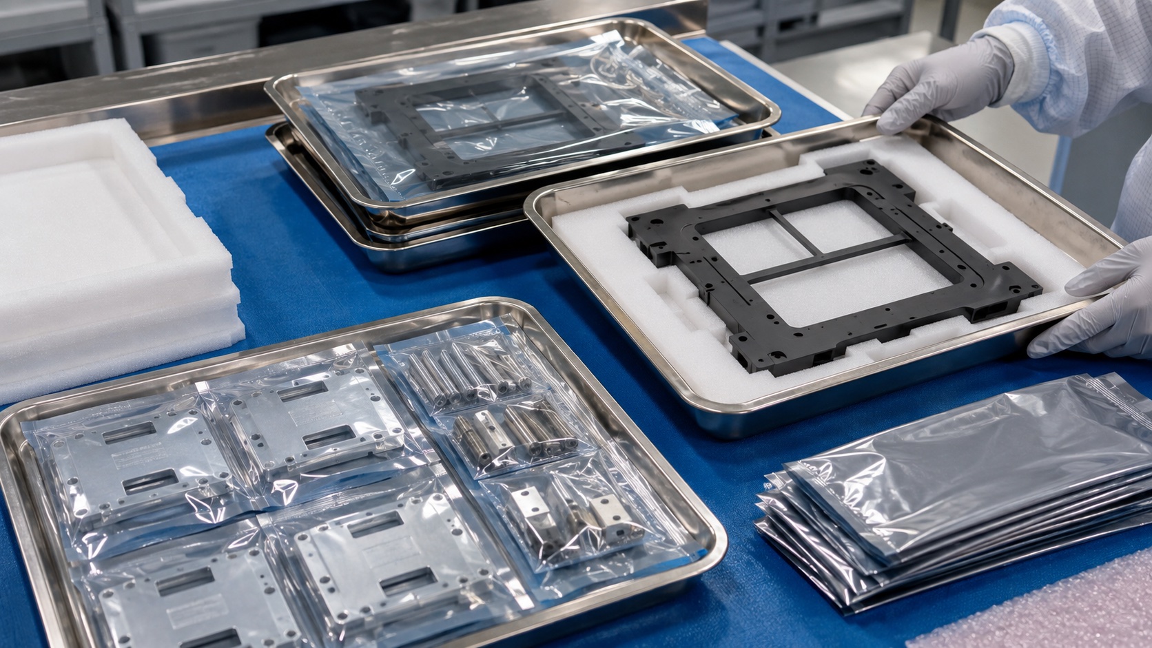
After machining and finishing, remove chips, coolant and coating residue from pockets, threaded holes, slots and insert locations. Separate plates with protective sheets or trays so precision faces, coated surfaces and dowel holes cannot rub. Labels should identify part number, revision, material lot, finish lot and inspection status. Packaging should be clean and protective without claiming sterility unless a validated sterile process is part of the order.
FAQ
Can a machined mount plate validate imaging performance?
No. It provides controlled geometry; imaging calibration, radiation performance and system validation remain with the equipment manufacturer.
Which features are usually critical?
Primary mounting faces, dowel holes, detector or collimator hole patterns, flatness zones, insert locations and masked contact areas are commonly critical.
How should flatness be specified?
Define the support condition, measurement method and whether the plate is checked free-state or restrained with a torque pattern.
Does coating affect precision holes?
Yes. Anodizing or other finishes can change dowel fits, threads and insert locations, so masking and post-finish inspection should be planned.
How is distortion controlled?
Balanced roughing, supported fixturing, relaxation between operations and free-state inspection help control broad or pocketed plates.
What should be in the RFQ?
Send drawings, 3D models, datum requirements, material, finish, critical tolerances, inspection records, masking needs and packaging requirements.