
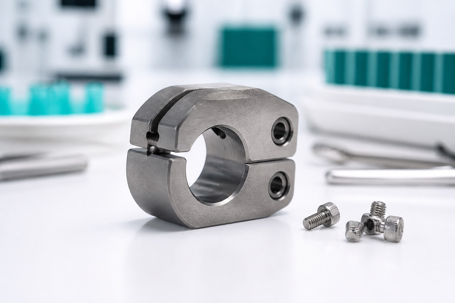
Ti-6Al-4V Ultrasound Probe Locking Clamp: Precision CNC Machining Case
Representative application
This case describes a representative Ti-6Al-4V locking clamp used in an ultrasound probe positioning or service fixture. The part provides a pivoted or bolted hold-down surface while keeping the probe lens, cable exit and reference faces accessible. It is a manufacturing example for fixture hardware, not a certified medical device component. The equipment manufacturer defines the fixture use, allowable clamp load, probe protection method and process validation.

Released package review
The controlled package includes a 2D drawing, 3D model, revision, titanium grade, finish, deburr notes, thread requirements and critical dimensions. Before quoting, the shop reviews contact face width, clamp arm stiffness, pivot or screw location, access for small cutters, edge break limits and whether any surface touches a finished probe housing. If a pad, insert or coating is required, it should be defined before first article.
Material control
Ti-6Al-4V offers strength, low density and good corrosion resistance, but it requires suitable tool paths, cooling and tool-life control. Material certificates and heat lot identity should remain linked to the traveler. Stock orientation, blank size and roughing strategy are selected to leave enough material for final cleanup on the contact face, pivot bore and mounting areas.
CNC machining sequence
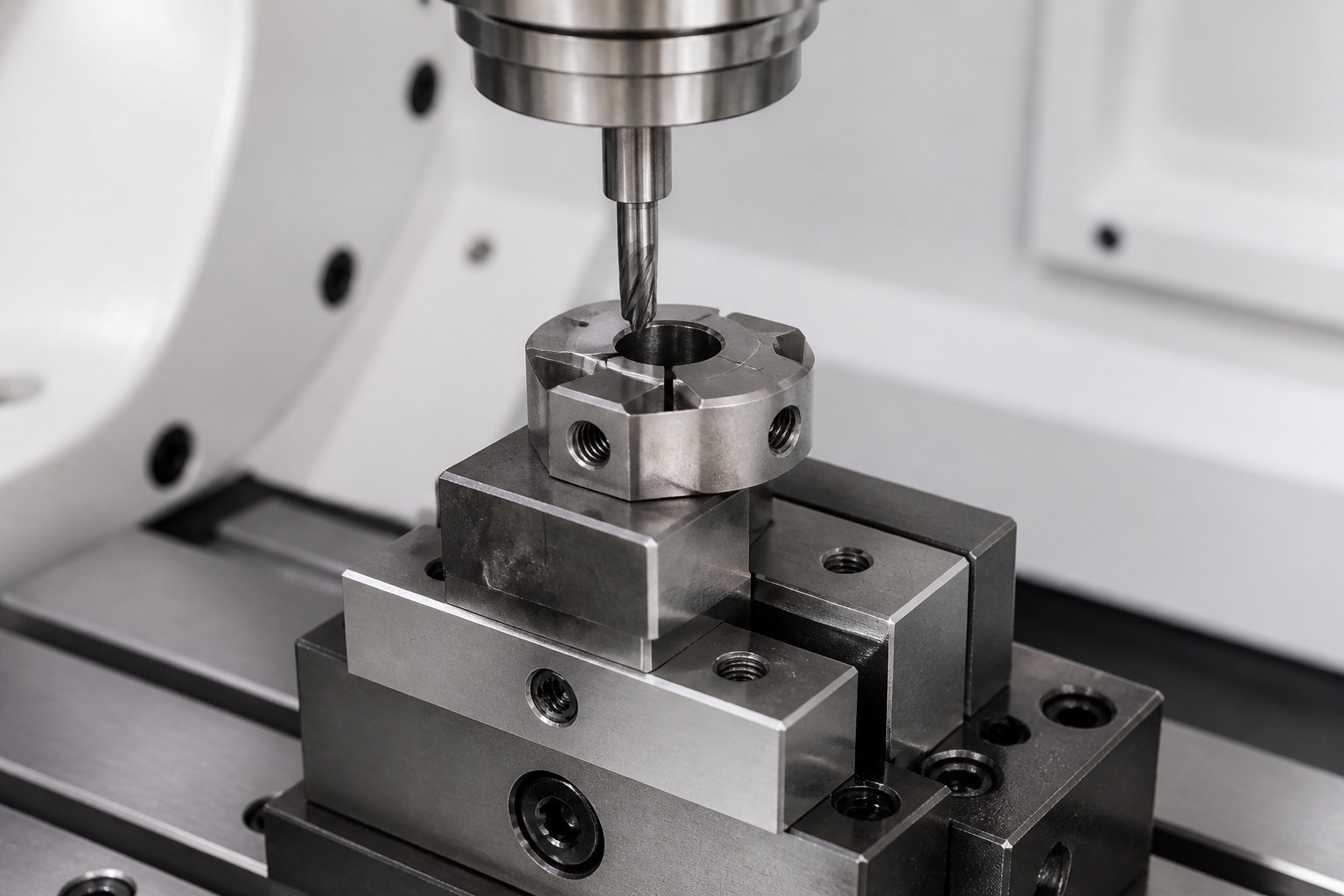
The first setup establishes the mounting datum and roughs the outside profile. Later operations finish the clamp contact face, pivot bore, screw counterbores, slots and relief features from controlled references. Tool wear is watched closely because titanium can produce heat and edge degradation that affects burrs or surface finish. Thin arms are left supported as long as possible before final profiling.
Contact and edge control
The contact area should hold the probe or insert repeatably without sharp edges. Corner radii, edge breaks and surface finish are controlled separately from noncontact exterior surfaces. Burrs around slots, pivot holes and threaded features are removed without rolling the contact face. If a soft pad is bonded or assembled later, the machined geometry should support its location and replacement.
Inspection package
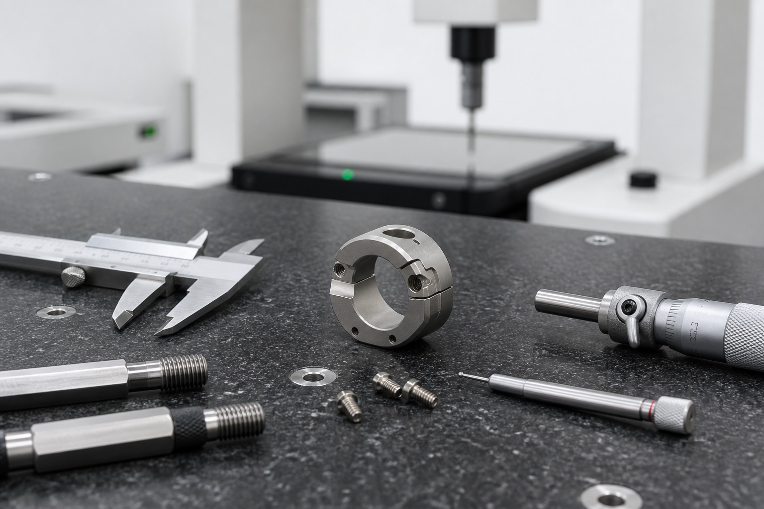
A first-article report can include material certificate, dimensional report, contact face flatness, pivot bore position, slot width, screw pattern, thread checks, surface review and representative photos. CMM inspection verifies datum relationships; optical inspection is useful for edges and small slots. If a master probe or fixture gauge is supplied, a functional fit check can be recorded separately.
Cleaning and packaging
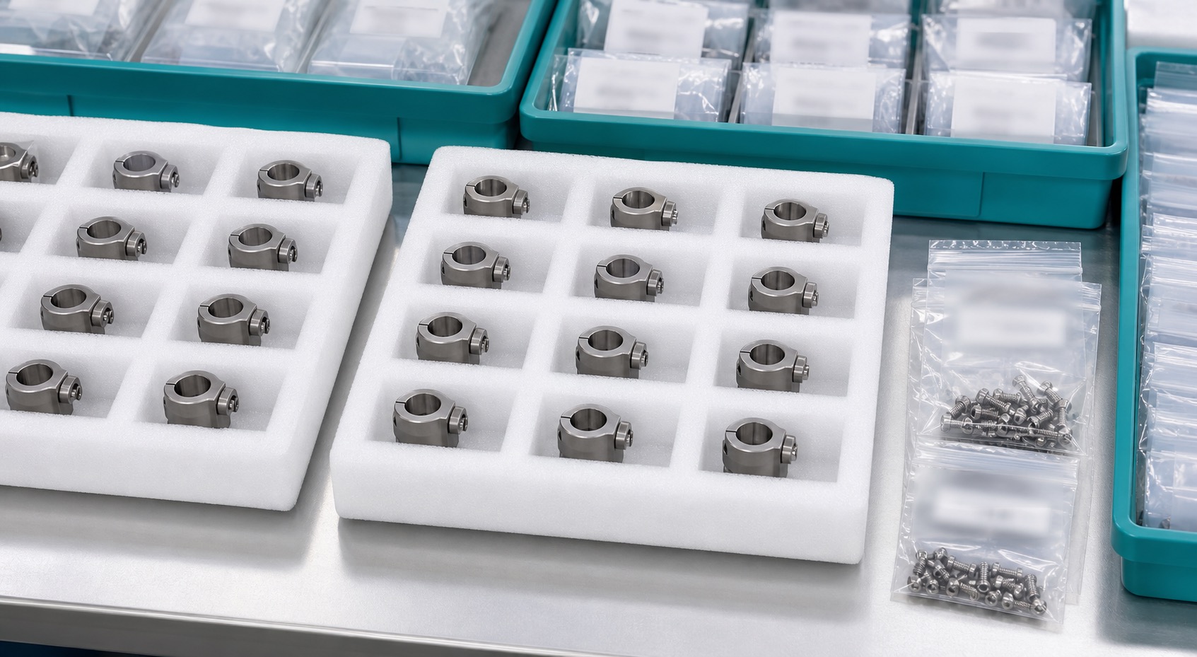
After machining and inspection, titanium chips, cutting fluid and loose particles are removed from threaded holes, slots and relief pockets. Finished contact areas are protected from dents and rubbing. Parts are separated in trays or bags, labeled by part number, revision, material lot and inspection status. Packaging is clean and protective but does not imply sterility unless a validated process is specified.
Repeat production controls
For repeat batches, the process controls include CNC program, fixture, cutter life, deburring method, inspection plan, cleaning and packaging. Trend checks on contact face flatness, pivot location and slot width help detect drift. Any change to pad material, probe geometry, clamp torque or fixture base should trigger a drawing and process review.
Customer handoff
The customer handoff includes approved first-article data, batch quantity, required certificates, inspection format, cosmetic criteria and any customer-supplied assembly test. Clear acceptance criteria prevent the clamp from becoming a source of variation in ultrasound probe handling or measurement.
FAQ
Is the clamp implanted or patient contacting?
No. This representative clamp is fixture hardware for probe handling or positioning, not an implant or patient-contact component.
Why choose Ti-6Al-4V?
It offers strength and low mass, but the final material choice must match the fixture load, cleaning exposure and customer specification.
Which dimensions are most important?
Contact face flatness, pivot bore location, screw pattern, slot width, clamp height and edge condition usually drive function.
How are probe surfaces protected?
The design may use controlled radii, defined contact patches, soft pads or inserts specified by the device or fixture owner.
What inspection records are useful?
Material certificate, dimensional report, thread checks, surface review, photos and any agreed functional fit check can accompany the parts.
Can the supplier define the clamp force?
The machining supplier can advise on manufacturability, but allowable clamp load and validation are defined by the equipment manufacturer.