
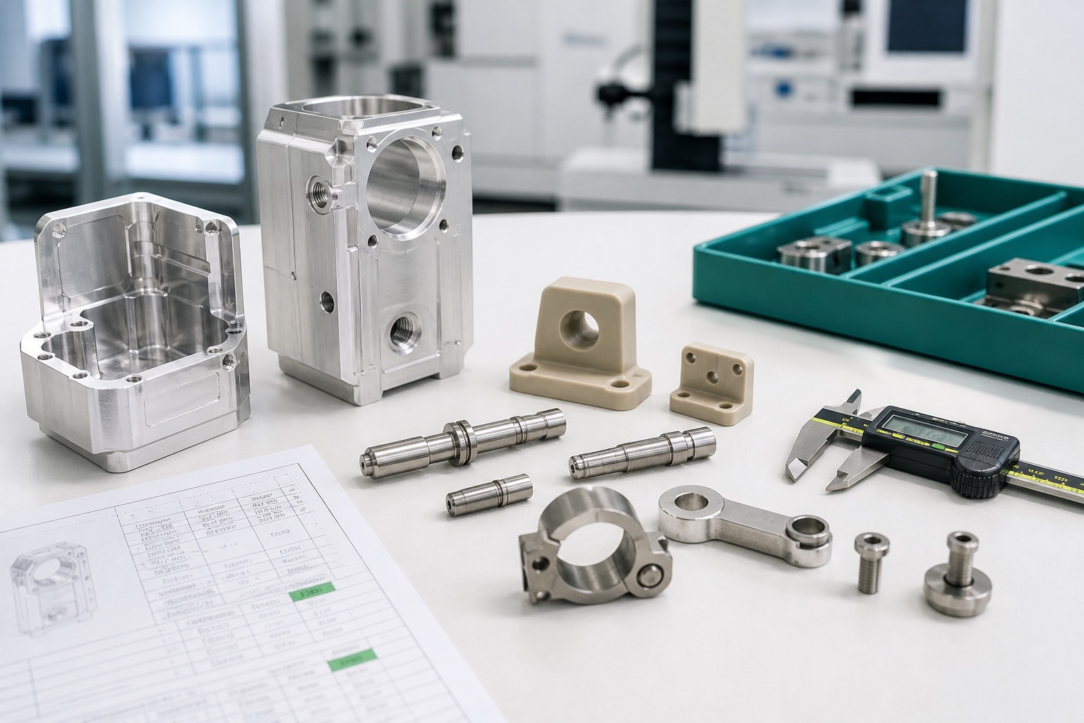
CNC Machining Medical Device Control Housings: Datums, EMI Interfaces, Sealing and Inspection
Why control housings need more than cosmetic machining
Medical device control housings protect electronics, connectors, displays and user-interface hardware while also supporting sealing, grounding and repeatable assembly. A machined enclosure may appear to be a simple box, but it can define board position, connector flushness, EMI contact, gasket compression and service access. If a pocket is warped or a connector wall is thin, the completed device may require extra assembly adjustment. The machining plan should therefore treat the housing as a functional electromechanical interface.

Start with the assembly stack
Before quoting, review the circuit board, display, keypad, connector, cable gland, gasket and cover stack. The drawing should define which faces locate the PCB, which bosses control screw preload, which surfaces contact shielding fingers and which edges are cosmetic. A datum system based only on the outside contour can hide a shift between the board, connectors and cover. The supplier needs the critical assembly interfaces, not only an exported solid model.
Material and finish planning
6061-T6 aluminum is often selected for medical control housings because it machines predictably, keeps weight manageable and accepts anodizing. Stainless steel or engineering plastics may be chosen for other designs. The device manufacturer should specify alloy, certificate needs, finish, color, masking and post-finish dimensions. Anodizing can change small threads, gasket grooves and connector fits, so allowance and inspection after finish must be planned.
EMI and grounding interfaces
Some medical electronics housings use conductive contact surfaces, ground screws or shielding features. These areas should be called out separately from cosmetic surfaces because coating, masking and surface roughness matter. If a contact patch must remain conductive, the drawing should define masking or post-finish treatment. Inspection should confirm both location and visible condition of the contact surface, while electrical performance validation remains with the equipment manufacturer.
Sealing and gasket grooves
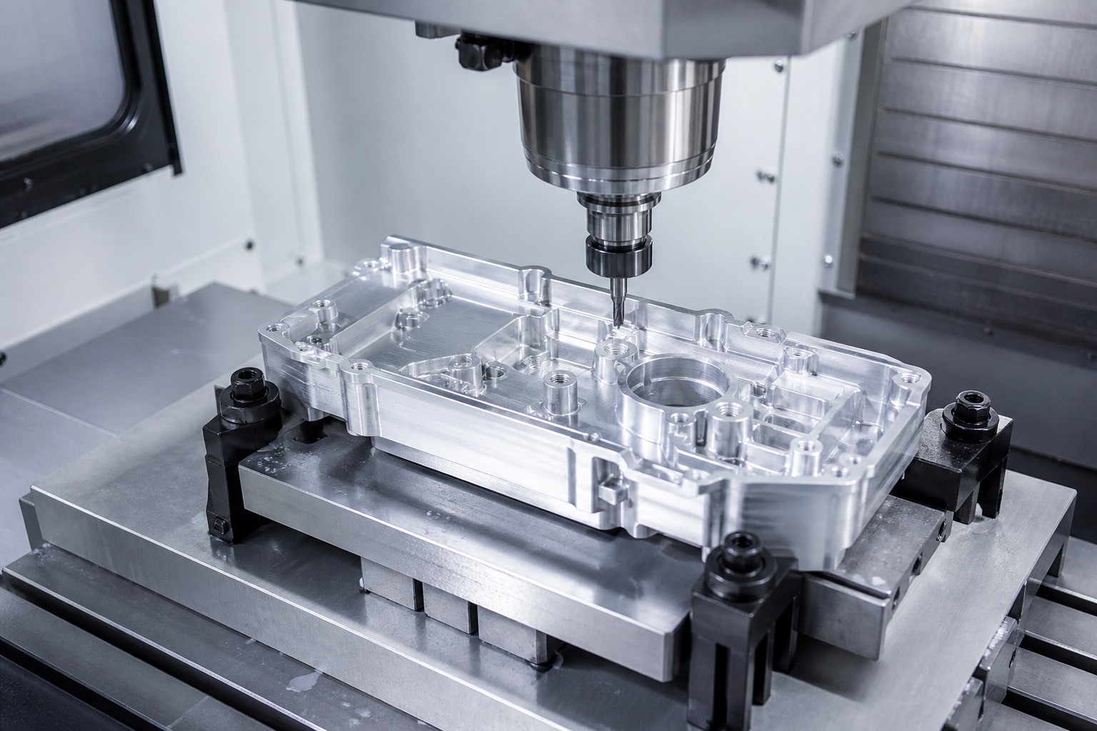
Control housings may need protection against cleaning fluids, dust or repeated handling. Gasket grooves and cover lands require controlled depth, width, radius, flatness and screw pattern relationship. Over-deburring can round a sealing wall, while coating buildup can alter compression. The drawing should define support condition for flatness measurement and clarify whether dimensions apply before or after finishing.
Machining sequence and distortion control
A stable process usually roughs the main pocket, establishes PCB and connector datums, then finishes cover lands, bosses and gasket grooves from controlled references. Thin walls and large pockets can move as material is removed. Balanced roughing, supported fixturing and inspection after unclamping help reveal spring-back. Tool marks in cosmetic zones and burrs near cable or button openings should be controlled without altering functional geometry.
Inspection and documentation
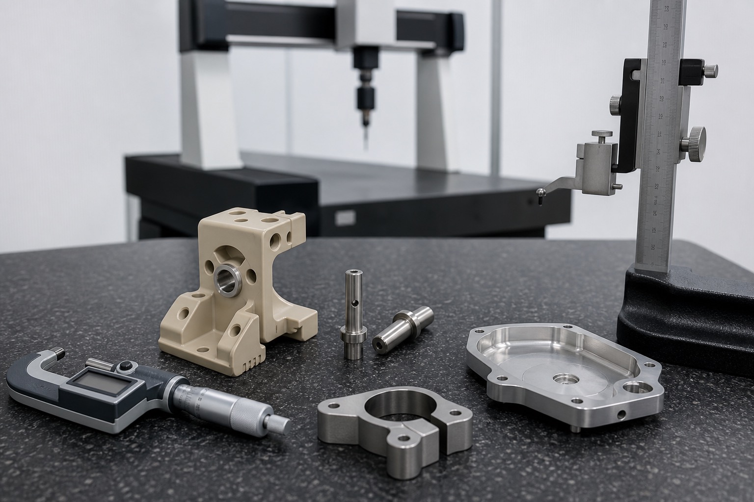
A first-article plan can include CMM checks for board bosses and connector windows, optical measurement for gasket grooves, thread gauges, flatness checks, coating review and photos of EMI or masked areas. Results should be linked to material lot, program revision, fixture revision and finish batch. Prototype assembly feedback should be compared with the dimensional report so tolerance changes are based on evidence.
Cleaning and packaging
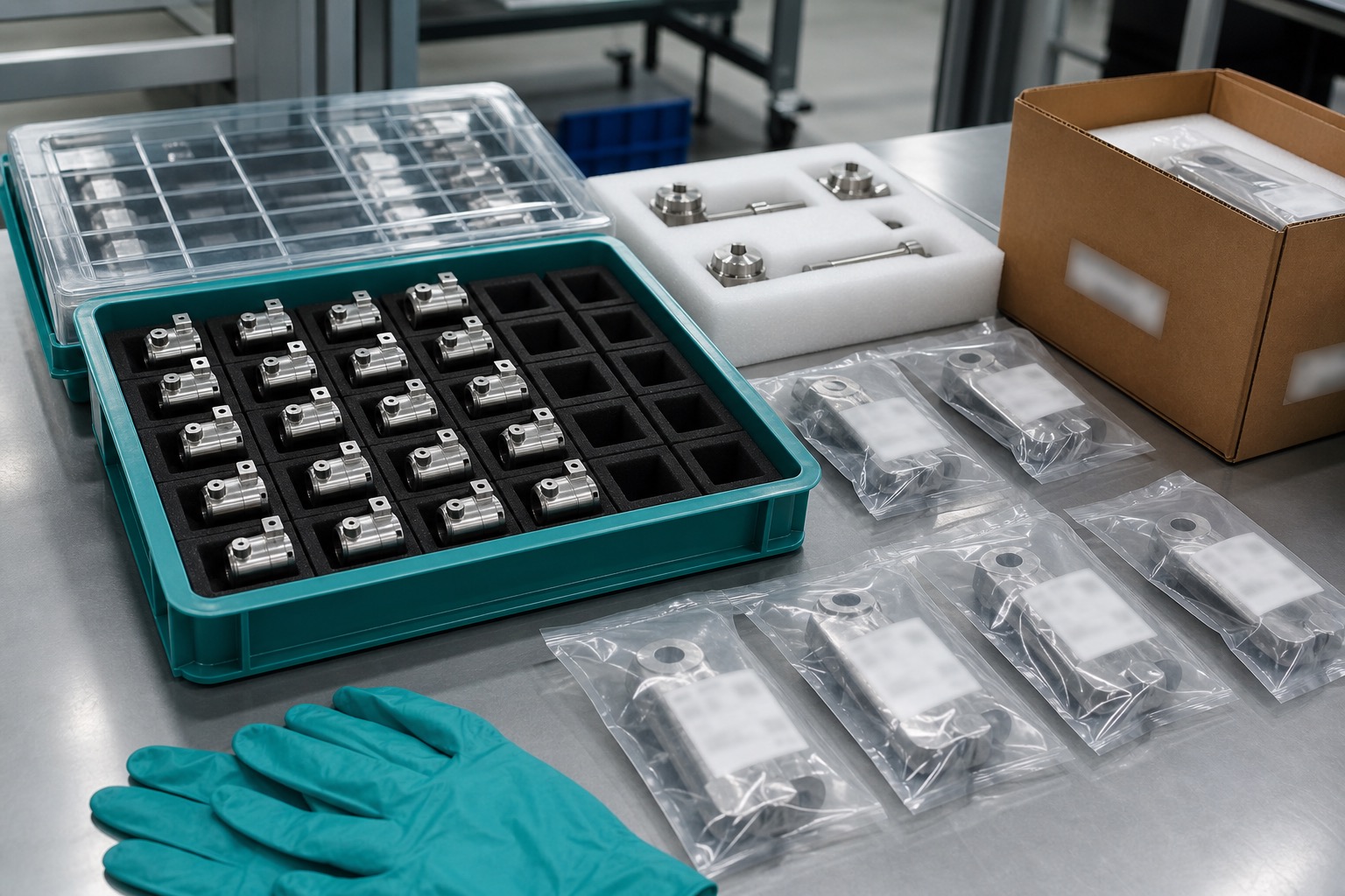
After machining and finishing, remove chips, coolant, abrasive residue and coating dust from threaded holes, pockets, grooves and connector openings. Parts should be separated so cosmetic faces, seal lands and contact surfaces cannot rub. Labels should identify part number, revision, material lot, finish lot and inspection status. Packaging should not claim sterility unless a validated sterile process is included.
RFQ handoff
A useful RFQ includes drawings, 3D models, board and connector interface details, material and finish, masking requirements, gasket data, critical tolerances, prototype and production quantities, cleanliness level, inspection records and any assembly or environmental test method supplied by the customer. Clear inputs let the machining supplier identify access, fixture and finishing risks before production.
FAQ
Can a machined housing validate a medical device?
No. It provides controlled mechanical interfaces; electrical safety, EMC, usability, sealing and device validation remain with the equipment manufacturer.
Which features are usually critical?
PCB bosses, connector windows, display openings, gasket grooves, cover lands, EMI contact areas and assembly datums are commonly important.
Why plan anodizing early?
Coating can change threads, grooves and fitted details. Masking, allowance and post-finish inspection must be defined before production.
How are EMI contact areas handled?
They should be identified separately, with masking or surface treatment specified by the device designer and verified visually or dimensionally as needed.
How is distortion controlled?
Balanced machining, supported fixturing, free-state inspection and post-finish checks help manage thin walls and large pockets.
What should be in the RFQ?
Send drawings, models, board and connector requirements, material, finish, gasket data, quantities, tolerances, inspection and cleaning needs.