
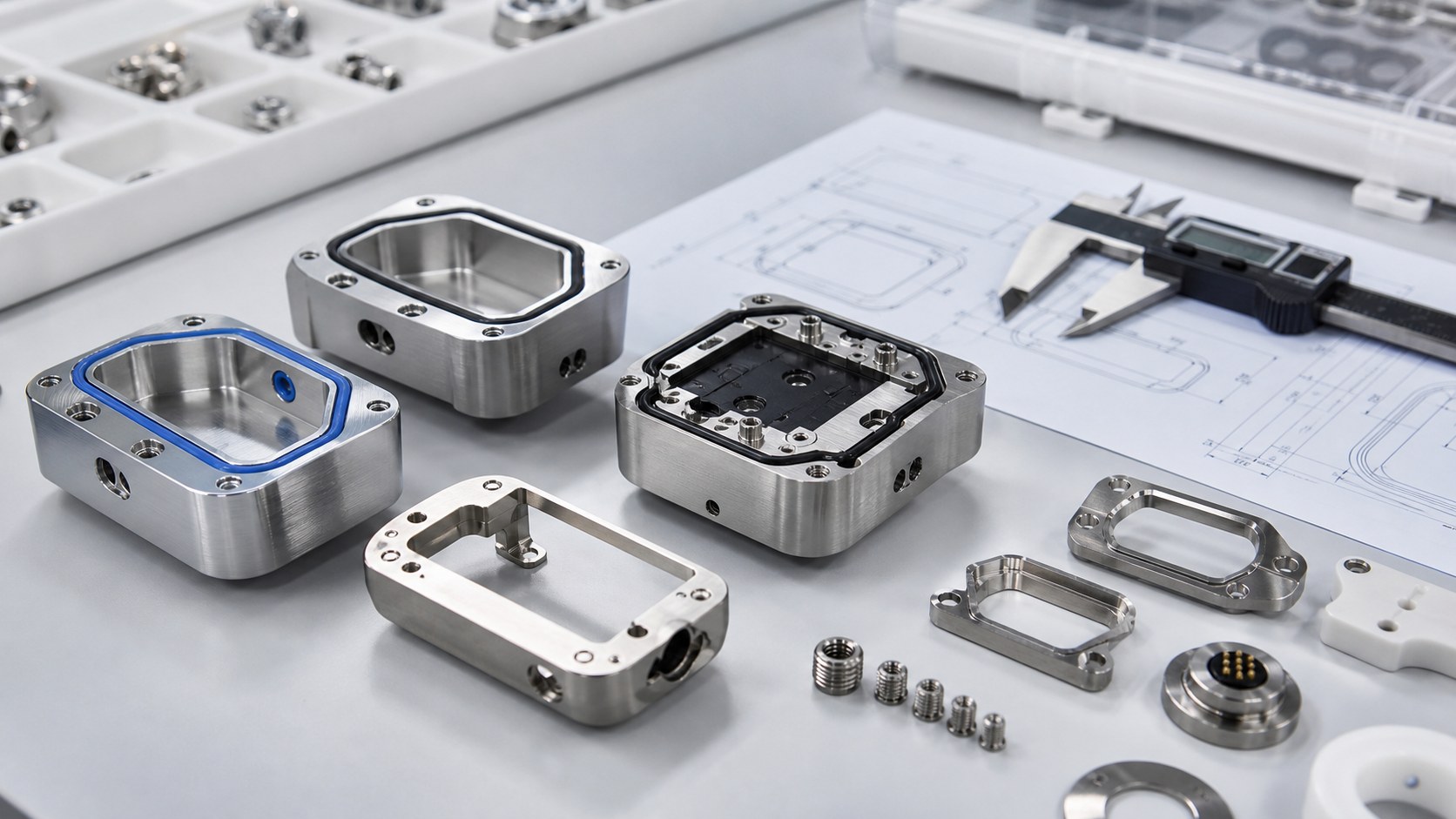
CNC Machining Wearable Medical Monitor Housings: Seal Grooves, Sensor Windows and Clean Packaging
Why wearable monitor housings need process discipline
Wearable medical monitoring devices must be light, comfortable and robust while protecting sensors, electronics, seals and charging interfaces. The CNC-machined housing or cover may not touch the patient directly in every design, but it often defines sensor window position, gasket compression, screw preload and cosmetic feel. Small variation in wall thickness, flatness or groove depth can affect assembly yield and environmental sealing. Treat the part as a controlled device interface rather than a decorative shell.

Define the sensor and skin-side references
The drawing should identify sensor windows, electrode openings, optical apertures, charging pads, buttons and any surface that locates against a strap or adhesive patch. A cosmetic outside contour is rarely enough as a datum. Sensor features should be related to assembly datums that also work for inspection and fixture design. If the design uses a replaceable back cover, a reusable module or a disposable adhesive interface, that use case changes material, finish, cleaning and documentation needs.
Material and finish choices
Aluminum alloys such as 6061-T6 are often selected for lightweight housings, predictable machining and durable anodized surfaces. Stainless steel or engineering polymers may be better for other requirements. The device manufacturer should define material grade, finish, color requirements, masking, coating thickness and whether dimensions apply before or after finishing. Anodizing can change small grooves and fitted details, so allowances and post-finish inspection must be planned.
Seal grooves and environmental protection
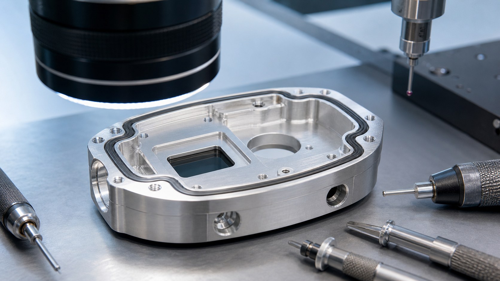
Wearable devices may face sweat, cleaning wipes and repeated handling. O-ring or gasket grooves require controlled width, depth, corner radius, surface finish and relation to screw bosses or clips. A groove that is too shallow can over-compress a seal; one that is too deep may fail to seal. The drawing should distinguish functional sealing lands from cosmetic chamfers and should state which dimensions are critical to enclosure performance.

Thin-wall machining and fixturing
Housings and rear covers often include thin ribs, pockets and large shallow surfaces. Fixturing must support the part without leaving marks or temporarily flattening a surface that springs back later. Balanced roughing, stable datum transfer and controlled final passes reduce distortion. For prototypes, it is useful to inspect the free-state part after unclamping and after finishing so the team can see how much movement comes from machining versus coating.
Burrs, edges and user contact
Edges near straps, charging contacts and sensor openings must be safe to handle while still preserving functional geometry. A blanket deburring rule may round a gasket wall or alter a button opening. Define different edge conditions for user-contact edges, seal lands, screw holes and internal pockets. Magnified inspection helps verify that no burrs or chips remain near sensor windows, threaded features or adhesive-contact areas.
Inspection plan
A first-article plan can combine CMM checks for datum relationships, optical measurement for windows and grooves, flatness checks for seal lands, thread gauges and cosmetic review under agreed lighting. The report should state measurement condition, finish state and fixture method. Inspection records are most useful when tied to material lot, CNC program, fixture revision, anodizing batch and any approved deviation.
Cleaning, packaging and traceability
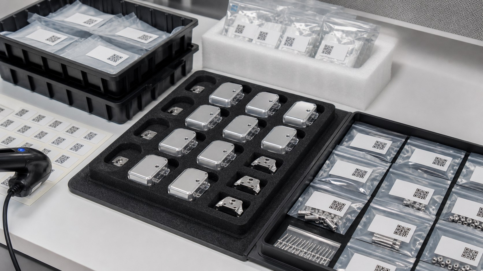
After machining and finishing, remove coolant, abrasive residue, coating dust and loose particles from pockets, threads and grooves. Parts should be separated so cosmetic surfaces, seal grooves and sensor-window edges cannot rub in transit. Labels should identify part number, revision, material lot, finish lot and inspection status. Packaging should not claim sterility unless a validated sterile process is included.
RFQ handoff
A useful RFQ includes drawings, 3D models, material and finish requirements, color or cosmetic standards, seal details, sensor window requirements, critical dimensions, prototype and production quantities, cleaning level, inspection records and any assembly or environmental test supplied by the customer. Clear inputs reduce hidden assumptions and help the supplier give manufacturability feedback before production tooling is locked.
FAQ
Can the housing prove wearable device performance?
No. The housing provides controlled mechanical interfaces; the device manufacturer validates sensors, electronics, software, sealing and clinical performance as a system.
Which housing features are usually critical?
Sensor windows, gasket grooves, seal lands, screw bosses, charging-contact areas, wall thickness and assembly datums are commonly important.
Why inspect after anodizing?
Coating can alter grooves, fitted features and cosmetic surfaces, so the drawing should define whether dimensions apply after finishing.
How are thin walls controlled?
Balanced machining, supported fixturing, free-state inspection and post-finish checks help manage distortion and spring-back.
How should cosmetic and functional edges differ?
User-contact edges may need smoothing, while gasket walls and locating edges may need controlled geometry without excessive rounding.
What belongs in the RFQ?
Send drawings, models, material and finish requirements, seal details, sensor references, quantities, inspection needs, cleanliness and test requirements.