
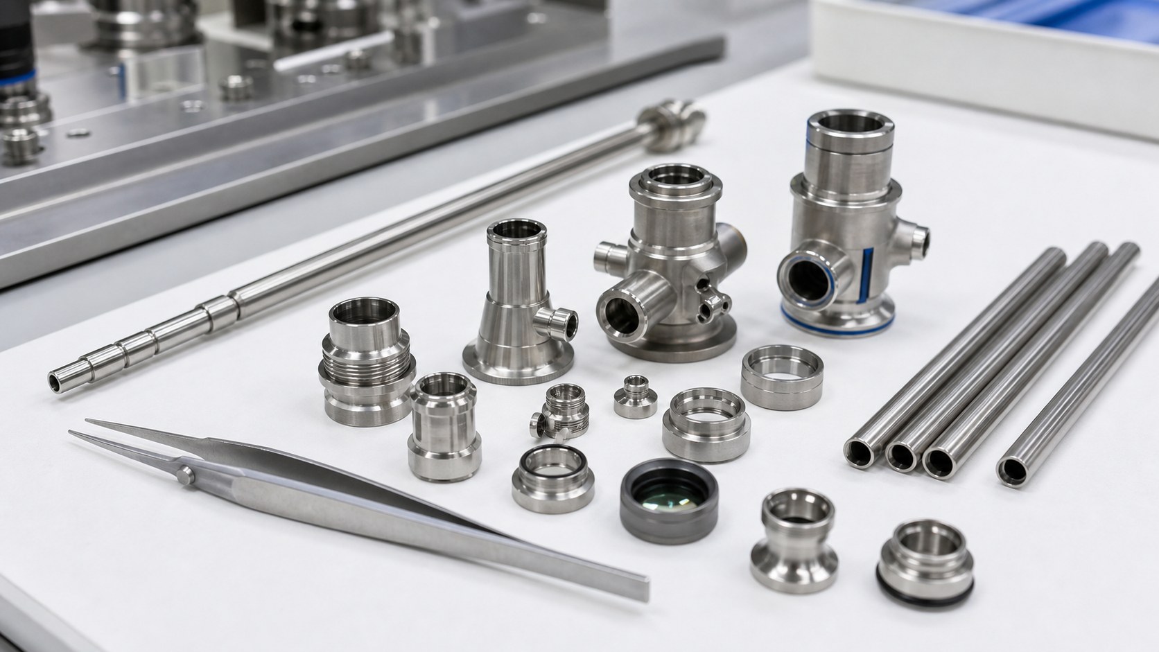
CNC Machining Endoscope and Laparoscope Components: Thin Walls, Lens Seats and Clean Assembly
Why endoscope CNC components are difficult
Endoscope and laparoscope assemblies combine optical alignment, thin-wall metal features, cable routing, fluid sealing and clean handling in a compact package. A machined lens housing, yoke, spacer or tube support may look simple, but it can control field of view, distal-tip geometry, illumination position and assembly repeatability. Small burrs, ovality, wall variation or groove drift can create problems that only appear during optical assembly. The machining plan therefore needs to protect functional references, not only achieve a nominal outside shape.

Define optical and mechanical references together
A useful drawing identifies the optical axis, lens seat, sensor or fiber reference, tube interface and assembly datum in one coherent system. If the optical center is referenced from one feature while CNC inspection uses another, a part can measure well but assemble poorly. Datum choices should be accessible to machining, CMM or optical inspection and final assembly. For prototype work, it helps to record how lens centering, tube roundness and yoke position interact rather than treating each tolerance as isolated.
Material and finish planning
316L stainless steel is often selected for corrosion resistance, cleanability and small medical instrument features. Other alloys or engineering polymers may be suitable when weight, stiffness, electrical isolation or imaging compatibility matter. The device manufacturer should define exact grade, certificate, passivation, electropolishing or coating needs. Finish thickness and edge rounding can affect lens seats, grooves, hinge bores and tube fits, so the drawing should state whether dimensions apply before or after finishing.
Thin walls and tube features
Thin-wall tube supports and distal housings require controlled clamping and balanced machining. Excessive jaw force can temporarily hide ovality, while one-sided material removal may release stress after the part is unclamped. Roundness, concentricity and wall thickness should be inspected in the state defined by the drawing. If a tube is later welded, crimped or bonded, the manufacturing review should include heat input, adhesive clearance and downstream cleaning access.
Grooves, seats and sealing details
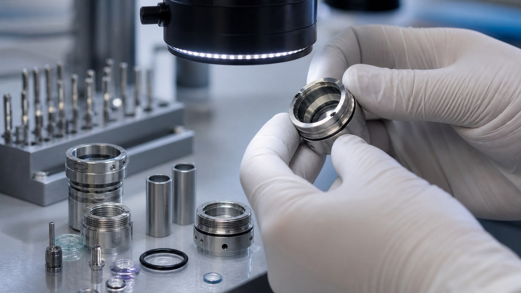
Lens retaining grooves, O-ring lands and cover interfaces need defined width, depth, radius and surface condition. A groove that is only a few hundred microns wide can be damaged by a broad deburring rule or by coating buildup. Seal lands should be tied to the same datums used by the mating cover or sleeve. When a feature is hard to measure after assembly, the inspection plan should capture it before it becomes hidden.
Burr and particle control
Endoscope components often contain slots, cross holes, thread starts and tiny pockets that trap chips. A loose burr can scratch an optical element or later become a particle inside the device. Deburring should be feature-specific: preserve sharp functional stops, clean bore entrances and avoid rounding lens seats. Magnified visual inspection, borescope checks and validated cleaning steps are often needed when direct access is limited.
Inspection strategy
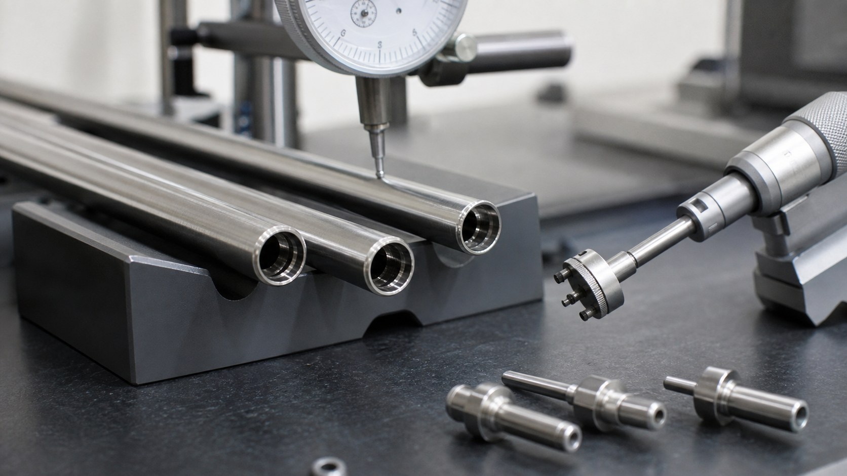
First-article inspection may include CMM checks for datum relationships, optical measurement for miniature grooves, roundness checks for thin tubes, pin gauges for bores and surface review under magnification. The report should state measurement condition, fixture method and sampling plan. Inspection data is most useful when linked to material lot, CNC program revision, fixture revision and finish batch so later assembly feedback can be traced to the correct process state.
Clean packaging and traceability
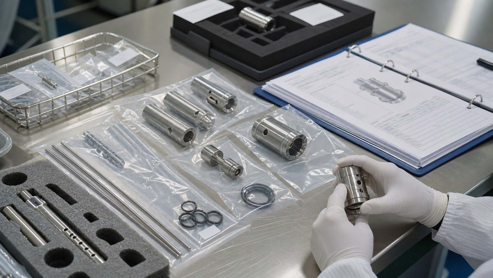
After machining and finishing, parts should be cleaned to remove coolant, polishing compound, metal fines and loose particles from every pocket and lumen-facing feature. Packaging should prevent functional edges, lens seats and tube interfaces from rubbing during shipment. Labels should show part number, revision, material lot and inspection status. Packaging should not be described as sterile unless the order includes a validated sterile process.
RFQ handoff
A complete request includes 2D drawings, 3D models, optical and mechanical datums, material and finish requirements, critical dimensions, expected prototype and production quantities, cleanliness level, inspection records and any customer-supplied assembly test. If optical alignment or leak testing is required, the device owner should define fixture, method and limits. Clear inputs allow machining feedback to improve the design before production risk becomes expensive.
FAQ
Can machining alone prove optical performance?
No. Machining controls mechanical interfaces; the device manufacturer validates optics, illumination, software, assembly and clinical performance as a system.
Which dimensions are usually critical?
Optical datum location, lens-seat geometry, tube roundness, bore position, groove size, seal lands and functional edge condition are commonly important.
Why specify before or after finishing?
Passivation, electropolishing or coating can affect miniature grooves, bores and edges, so the required measurement condition must be clear.
How are thin-wall parts inspected?
Roundness, concentricity, wall thickness and free-state geometry may be checked with optical, CMM and dedicated fixture methods.
How are hidden burrs controlled?
Use controlled tool paths, targeted deburring, magnified inspection, borescope access where needed and cleaning matched to the feature.
What should an RFQ include?
Send drawings, models, datums, material, finish, quantities, critical tolerances, cleanliness level, inspection needs and any assembly test.