
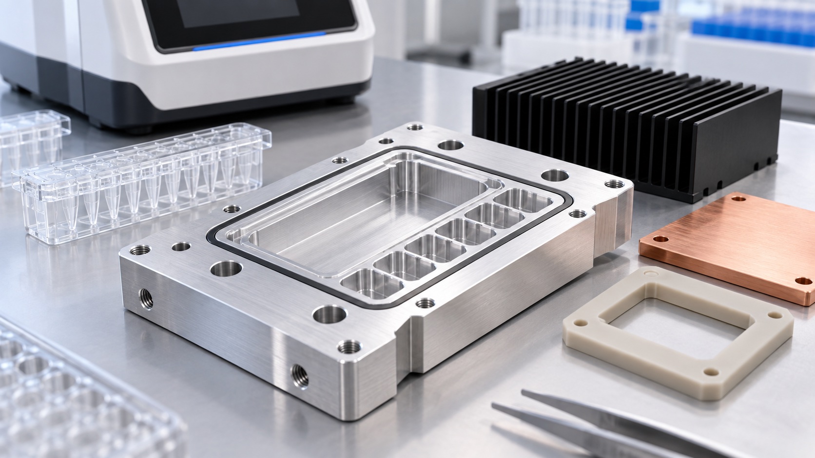
6061-T6 PCR Thermal-Cycler Sample Carrier: Precision CNC Machining Case
Representative application
This case describes a representative 6061-T6 carrier used to locate a multi-position consumable above a controlled heating and cooling assembly in a PCR instrument. It includes a precision well array, a flat mounting interface, a temperature-sensor pocket, fastener holes and locating features. It is a manufacturing example rather than a claim about a certified device or customer shipment. The instrument manufacturer owns thermal architecture, assay performance and final validation; the supplier controls the released material, CNC process, inspection, cleaning and delivery records.

Released manufacturing package
The controlled package includes a 2D drawing, matching 3D model, revision history, critical-characteristic list and coating or masking map. The drawing identifies the heater-side datum, two locating references, the well pattern, sensor pocket and screw interfaces. Before quoting, the shop reviews tool access, minimum wall thickness, burr-removal access, coating allowance and the measurement method for deep wells. Any missing thermal-test values, cleanliness class or consumable dimensions are returned for clarification.
Material and blank preparation
Certified 6061-T6 plate is selected with enough allowance for balanced roughing and final cleanup. Material identity remains linked to the traveler from cutting through shipment. Both major faces are rough-machined in stages to reduce the risk that one-sided stock removal pulls the carrier out of flat. The blank is allowed to stabilize before final datum work. If anodizing is required, the finish specification and masking boundaries are confirmed before the first article because well size and sensor fits may change.
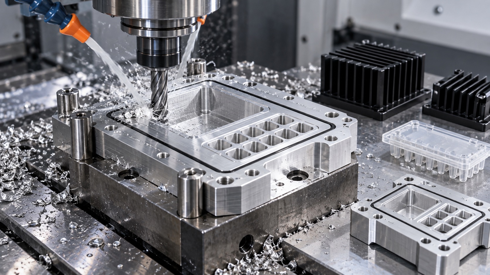
CNC setup and array machining
The first operations establish the mounting face and locating edges. The carrier is then supported on a fixture that limits distortion while allowing the well array to be machined from a consistent coordinate system. The process uses suitable drilling, reaming, form tooling or interpolation for the released geometry. Chip evacuation and tool-life limits are important across a dense pattern. Final passes on the wells, locating holes and sensor pocket occur after bulk material removal, and the free part is checked after unclamping.
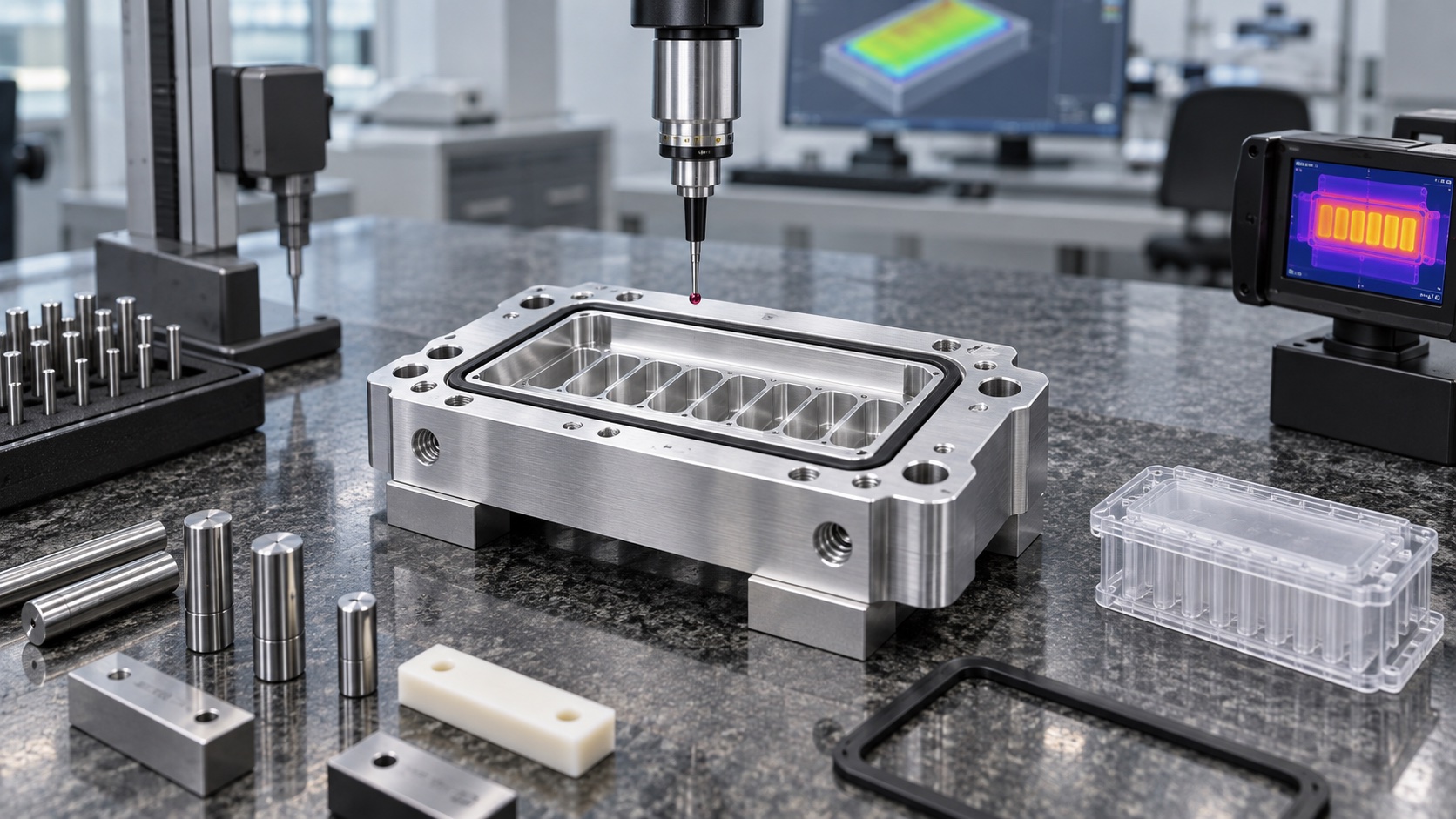
Datum and flatness control
The well pattern, locating pins and sensor pocket are inspected relative to the heater-side datum rather than to an arbitrary cosmetic edge. Flatness is measured in the state defined by the drawing, with support points and measurement strategy recorded. The screw pattern is reviewed together with the mounting face because uneven clamping can affect the thermal interface. Where a thin section remains around the wells, inspection includes local surface condition and evidence of handling dents or fixture marks.
Finish and post-process inspection
If the carrier is anodized, critical wells and fitted features are masked or controlled according to the approved finish map. The completed part is rechecked for well size, array position, flatness, sensor-pocket geometry and visible coating defects. Color variation alone is handled according to the agreed cosmetic standard, while scratches or coating buildup on a functional interface are evaluated against the drawing. Finish lot information remains tied to the material and machining records.
Cleaning and documentation
Every well and blind pocket is cleaned to remove coolant, chips, abrasive residue and loose coating particles. Inspection under suitable lighting or magnification confirms that the array is free of debris and burrs that could damage the consumable. A first-article package can include material certificates, dimensional results, array maps, surface photographs and finish records. These documents help the device manufacturer complete qualification, but they do not substitute for instrument-level thermal mapping or assay validation.
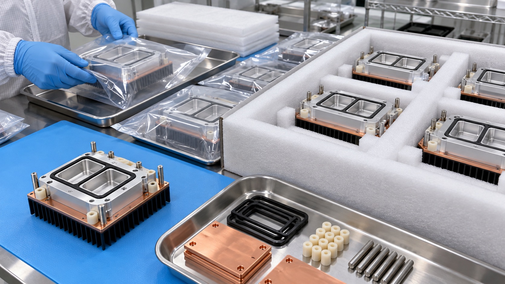
Packaging and repeat production
Finished carriers are separated in clean trays or protective bags so the well edges and flat mounting face cannot contact another metal part. Labels identify part number, revision, material lot, finish lot and inspection status. For repeat production, the CNC program, fixture, tool-life rules, inspection method, cleaning process and packaging specification remain under change control. Trend data for flatness, representative wells and array position can reveal process drift before assembly yield is affected.
Customer handoff
The production handoff defines prototype and batch quantities, approved sample results, consumable revision, required certificates and any customer-supplied thermal test procedure. Changes to consumable geometry, coating or mounting interface trigger a documented review because they may alter both manufacturing and device validation. A clear forecast helps reserve compatible material and finishing capacity, while a complete revision package prevents an obsolete well pattern from reaching the shop floor.
FAQ
Is this a certified PCR device component?
It is a representative machining case. Device certification, assay performance and system validation remain the responsibility of the PCR equipment manufacturer.
Why use 6061-T6 aluminum?
It offers useful machinability, mass and thermal conductivity, but the device designer must approve the alloy, finish and compatibility for the intended instrument.
How is array drift controlled?
The process uses a functional datum system, tool-life limits, in-process checks and final inspection of representative wells and pattern position.
Can anodizing change the wells?
Yes. Coating buildup can alter small diameters, so masking, process allowance and post-finish measurement must be defined.
Does the supplier perform thermal validation?
Only when the customer provides a controlled method and acceptance limits. Final instrument and assay validation belongs to the device manufacturer.
How are carriers protected for delivery?
They are cleaned, separated and packed to protect well edges and flat interfaces, with labels tied to revision, material, finish and inspection status.