
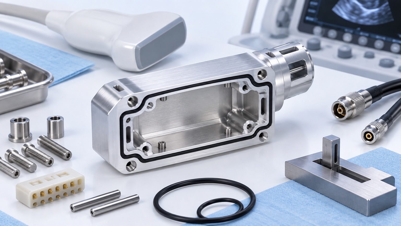
6061-T6 Portable Ultrasound Probe Connector Latch Housing: CNC Machining Case
Representative application
This case describes a representative 6061-T6 housing that supports a portable ultrasound probe connector insert, latch and cable strain-relief boot. The part includes an insert seat, keyed opening, latch stop, gasket groove, threaded bosses and a masked conductive band. It is a machining example rather than a certified-device claim. The ultrasound manufacturer remains responsible for electrical safety, EMC, ingress protection, cable durability, image performance and final validation. The supplier controls material, geometry, finish and agreed inspection records.

Released design package
The package contains a controlled drawing, matching solid model, revision history and critical-characteristic list. It identifies the primary connector seat, clocking face, latch interface, gasket groove, cable exit, cosmetic zones and anodize masking map. The customer supplies the connector insert, boot model, gasket definition, screw and torque requirements, and any approved fit fixture. Before quoting, the shop reviews cutter access, wall thickness, internal radii, coating allowances and inspection access.
Material and blank control
Certified 6061-T6 stock is received with lot documentation and machining allowance. Each blank remains traceable through machining, anodizing and packaging. The process reviews stock flatness and visible damage before setup. Material is removed in balanced stages to reduce movement around the large cavity. Any change to alloy, temper or stock form requires approval because stiffness, residual stress, color response and finished dimensions may change.
Machining sequence
The first setup establishes the connector seat and exterior datums, then roughs the central cavity while leaving support at the latch and gasket regions. A second controlled setup finishes the keyed opening, bosses, latch stop, cable exit and groove from the shared datum system. Tool paths limit burrs at thin windows and thread exits. The final contour and edge treatment protect cable and handling surfaces without rounding the insert seat or interrupting the sealing land.
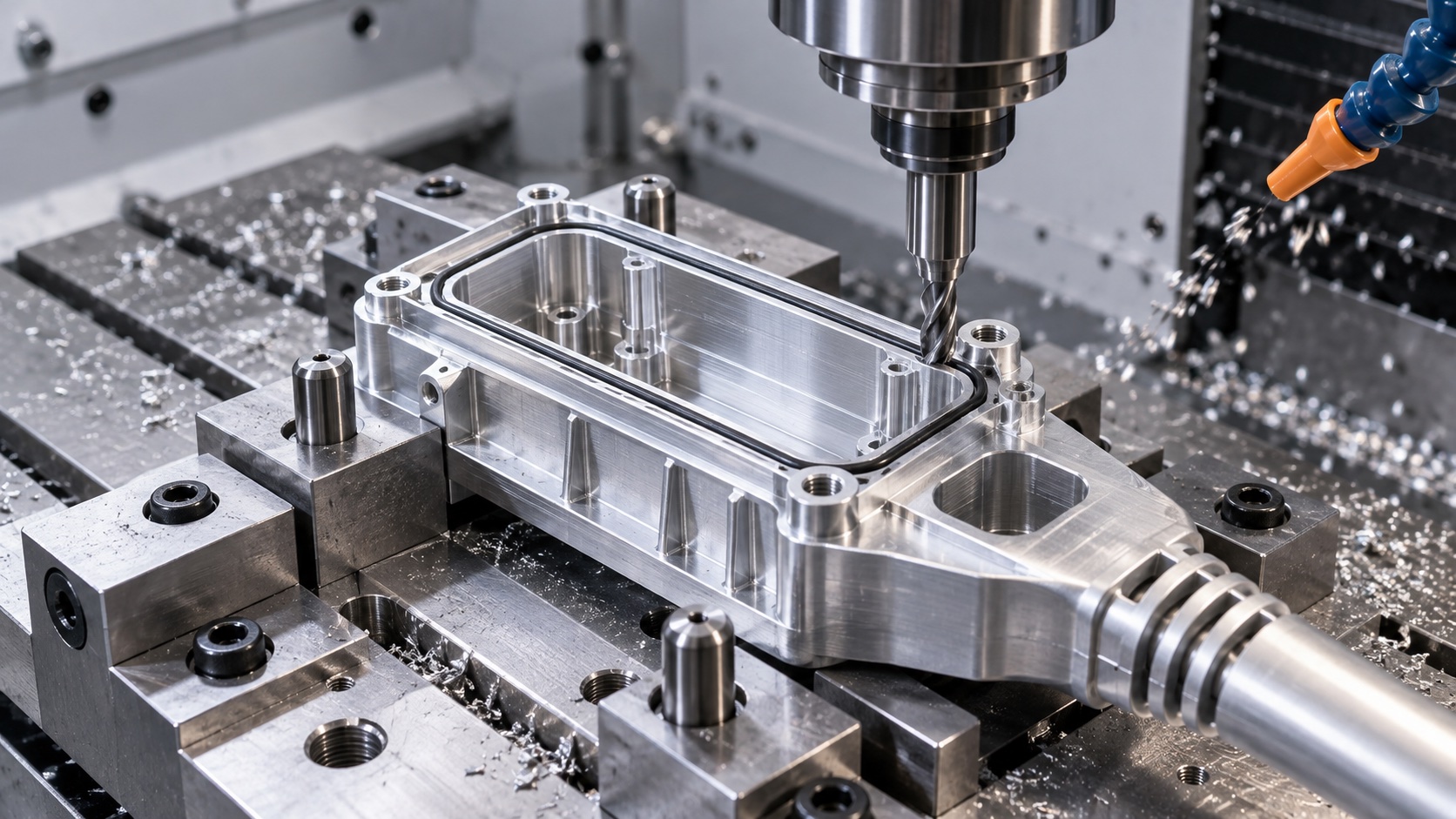
Latch and insert alignment
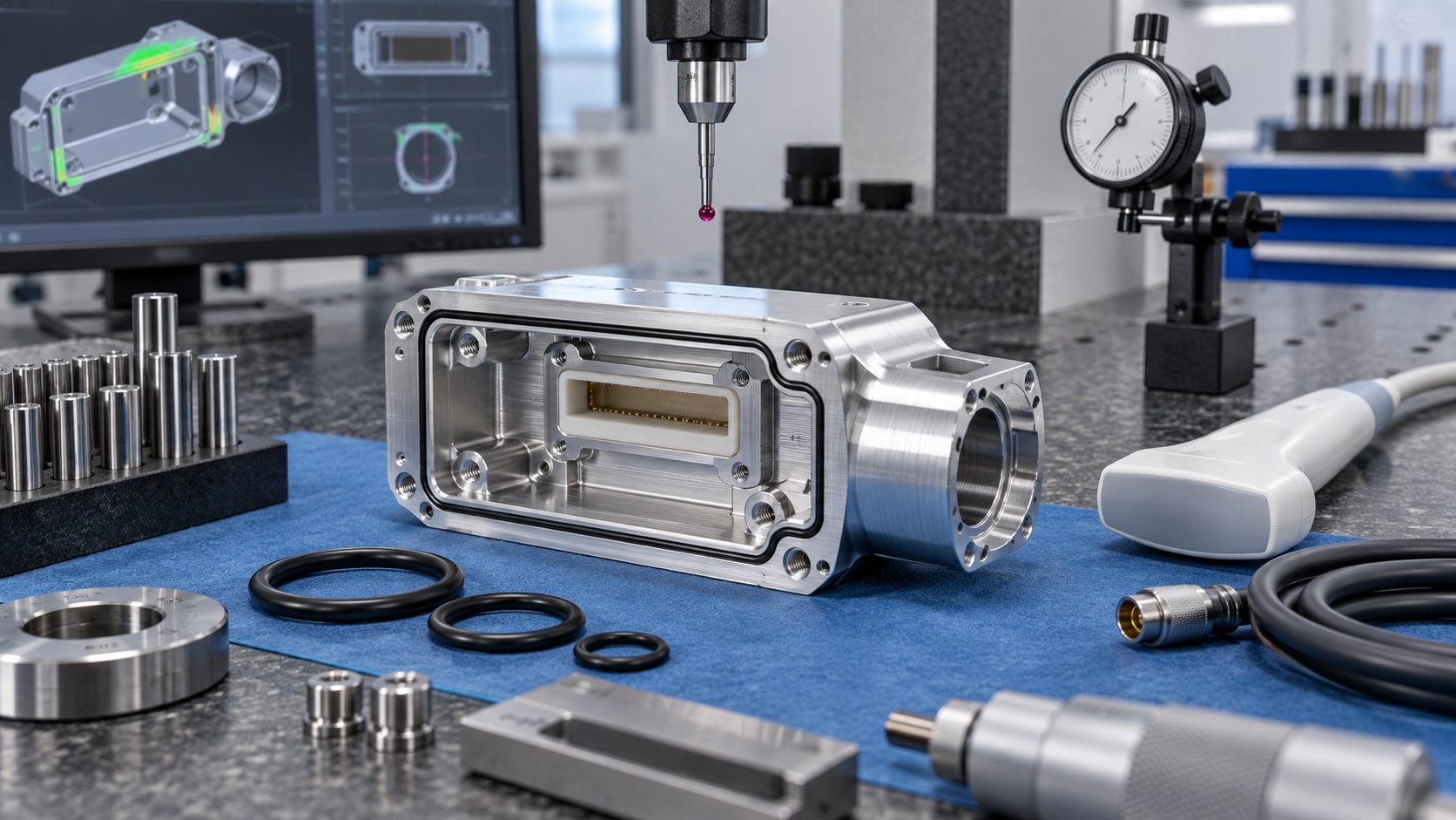
The latch stop and connector seat must hold the insert at the position specified by the equipment designer. CMM inspection relates the keyed opening, screw pattern and latch geometry to the primary seat. An approved insert or gauge can confirm assembly clearance and latch travel. Fastener torque and insert preload are customer-defined conditions. A successful fit check demonstrates mechanical compatibility only; it does not replace connector electrical, retention or lifecycle testing.
Gasket and conductive-band control
The gasket groove is checked for width, depth, corner radius, land flatness and absence of raised burrs. The conductive band is masked during anodizing according to the released map, with boundary position and surface condition inspected afterward. Threads and tight insert fits may also be masked or compensated. If coating creeps into a contact or sealing zone, rework follows an approved process rather than uncontrolled scraping that could damage the housing.
First-article inspection
The report includes material identity, connector-seat flatness and position, keyed-window profile, latch-stop location, boss and thread position, gasket groove, cable exit and masked-zone dimensions. CMM, optical measurement, thread gauges and a customer-approved fit fixture may be used. The report identifies pre- or post-finish condition, fixture, instrument and drawing revision. Cosmetic acceptance is documented separately from functional geometry so both are clear.
Cleaning and packaging
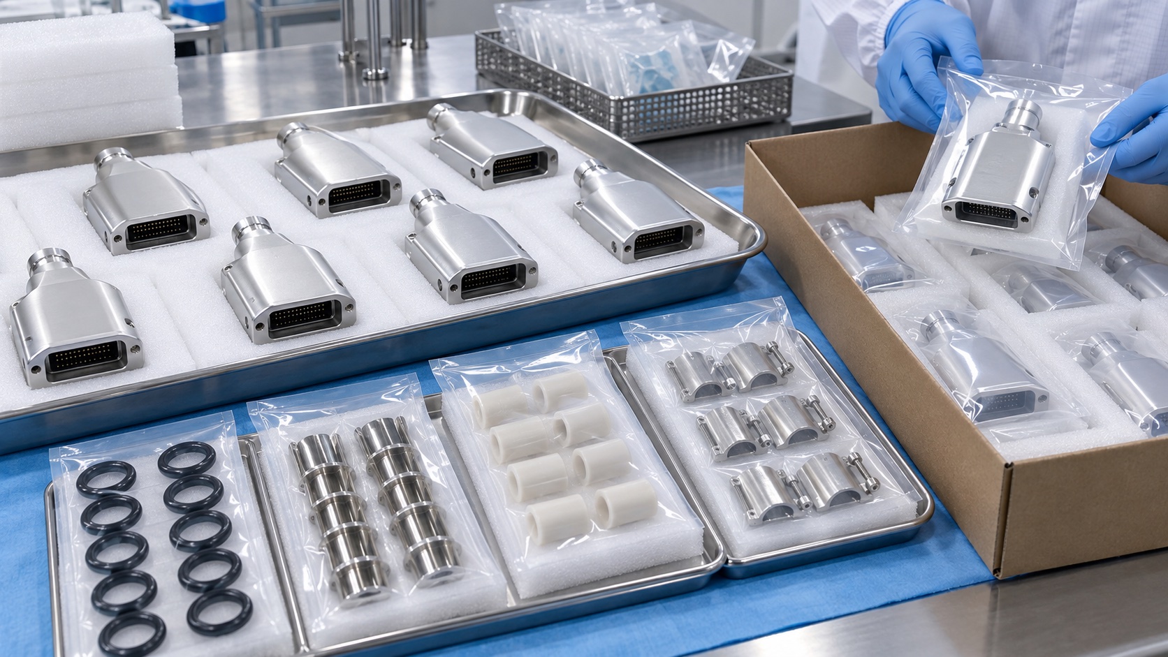
Finished housings are cleaned to remove chips, abrasive particles and loose anodize residue from cavities, grooves and threads. Each part is separated to protect the cosmetic shell, connector seat, gasket land and exposed conductive band. Labels identify part number, revision, material lot, finish lot, quantity and inspection status. Packaging is clean and protective, not sterile unless a separate validated process is specified. Mating inserts are shipped separately unless assembly is explicitly included.
Repeat-order control
For repeat production, the CNC program, fixture revision, masking map, anodize specification and inspection routine remain under change control. Trend data for seat position, latch stop and groove dimensions help detect drift. Forecast and batch size support traceable material and finishing capacity. Changes to the insert, gasket, boot, cable direction, latch, coating or torque trigger a documented customer review because they may alter the validated interface.
FAQ
Is this housing a complete ultrasound device?
No. It is a representative machined component. The equipment manufacturer validates and certifies the complete system.
Why use 6061-T6?
It can provide low mass, machinability and common finishes, subject to the product's structural, electrical, cleaning and durability requirements.
How is connector alignment verified?
The seat, keyed opening, screw pattern and latch stop are measured from common datums and may be checked with an approved mating gauge.
Why mask a conductive band?
Normal anodizing is electrically insulating; a defined uncoated or conductive area may be needed for the designed shielding and grounding path.
Does the groove inspection prove the seal?
No. It confirms component geometry. The assembled device must be tested with the final gasket, hardware and torque.
What documents can ship with the housing?
Material and finish certificates, lot traceability, first-article and dimensional reports, masking inspection and approved deviations can be supplied.