
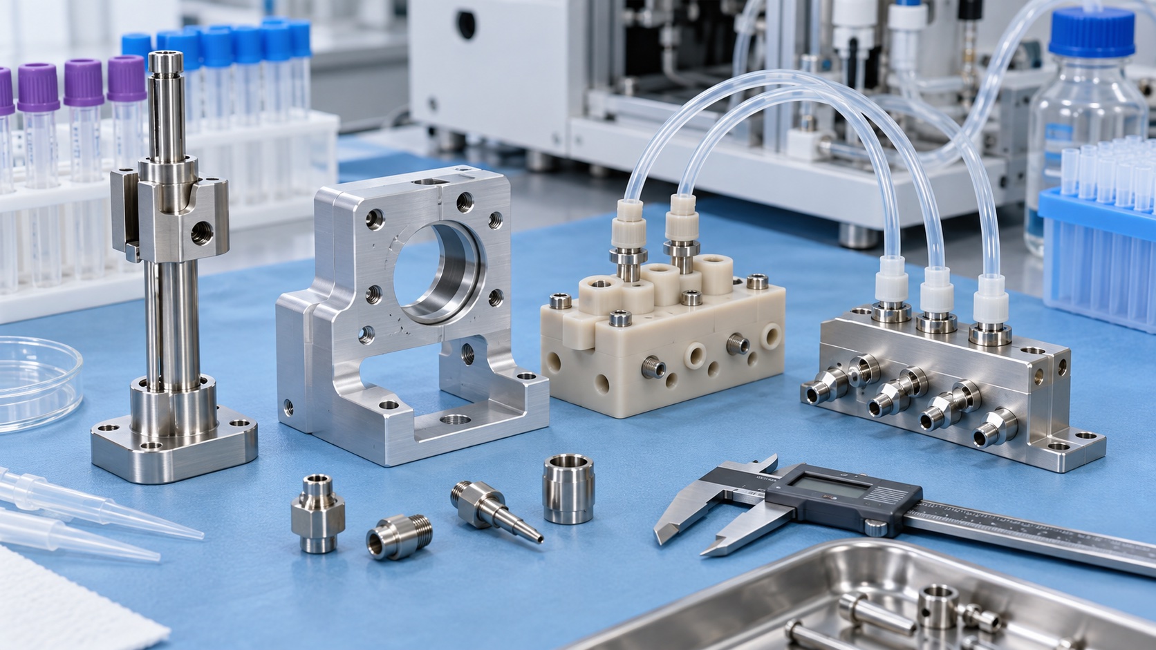
CNC Machining Hematology Analyzer Probe Interfaces: Alignment, Wash Clearance and Cleanability
Why the probe interface matters
An automated hematology analyzer repeatedly moves a sample probe between tubes, reaction areas and a wash station. The probe holder, guide, valve block and surrounding brackets determine how consistently the probe axis returns to those locations. Small angular or positional errors can reduce clearance, increase contact risk or make washing less repeatable. The machining supplier controls the released mechanical interfaces, but does not validate aspiration accuracy, carryover, analytical performance or biosafety. Those outcomes belong to the complete instrument, fluid path, software and customer validation.

Map the motion and fluid boundaries
The drawing review should follow the probe from its home reference to the sample tube and wash cup. Identify the surfaces that locate the holder, the axis that guides the probe, the travel envelope, splash zones and any features that contact reagent or wash fluid. Mark where tubing, seals and fittings connect to machined parts. A useful specification distinguishes wetted surfaces from structural surfaces and defines which edges must be accessible for cleaning. The shop should not infer fluid compatibility or disinfection chemistry from a general material callout.
Choose material for the actual environment
316L stainless steel is often considered for probe holders, collars and small fluid interfaces because it offers corrosion resistance and stable precision features. Aluminum or engineering polymers may be suitable for dry structural brackets, subject to the instrument design. The exact grade, condition, finish and certificate requirement must be stated. Cleaning chemicals, reagent exposure, passivation and galvanic contact with the probe or fasteners require design review. Keep material heat or lot identity tied to the production traveler and inspection record.
Create a common datum system
A probe holder normally needs a mounting face, lateral location and a bore or guide axis. Those features should be related through clear primary, secondary and tertiary datums. If the wash station is mounted to another frame, the drawing should define the shared reference chain rather than tolerancing each part independently. Avoid locating a critical probe axis only from a cosmetic outside contour. Accessible datum pads let CNC setups, CMM inspection and final assembly use the same coordinate system, reducing hidden stack-up.
Machine slender and small features carefully
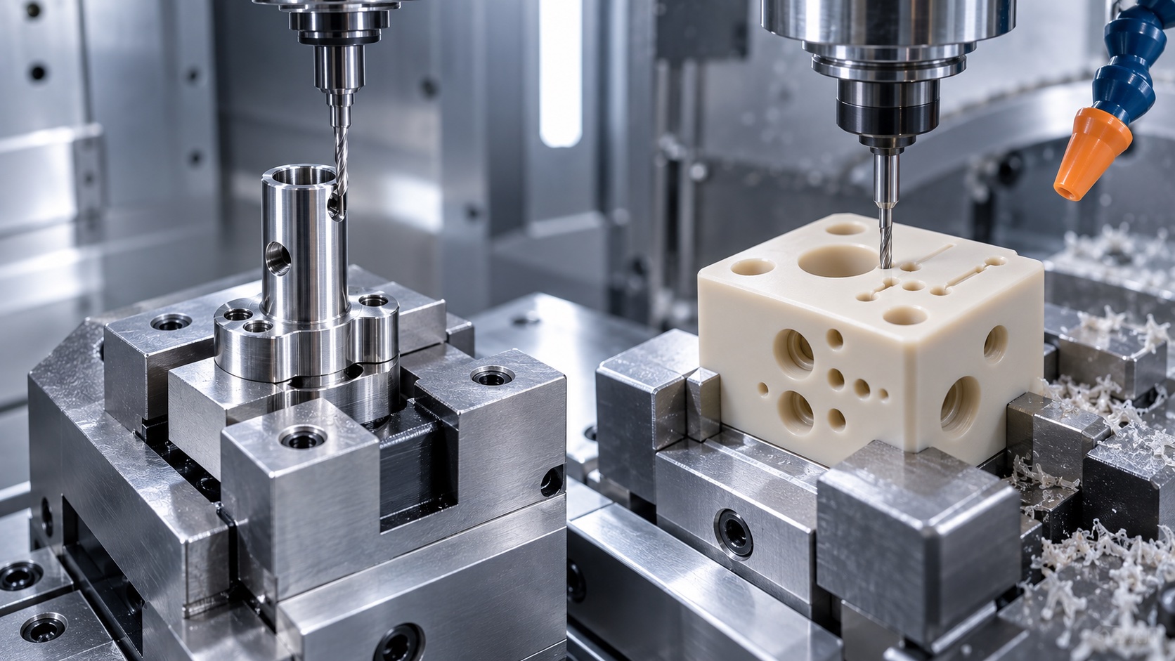
Long small bores, thin clamp arms and narrow wash channels need stable tooling and controlled chip evacuation. Roughing should leave support around the guide bore until critical faces are established. Sharp tools and suitable feeds reduce work hardening in 316L and limit burrs at cross holes. A split clamp must be finished in the defined free or assembled condition because tightening changes bore geometry. Edges near seals or tubing need specified breaks, while locating shoulders should not be rounded by generalized polishing.
Control coaxiality and clearance
The probe guide bore, clamp seat and wash-cup opening must preserve the clearance defined by the instrument designer over the complete travel. Bore size alone is not enough; axis position, straightness and perpendicularity to the mounting face also matter. Threads and fittings should not pull a fluid block out of alignment when tightened. If replaceable bushings are used, their installation force and final axis require verification. Customer-supplied probes, gauges or digital models can support fit checks without turning a trial assembly into an unsupported performance test.
Inspect cleanability-related details
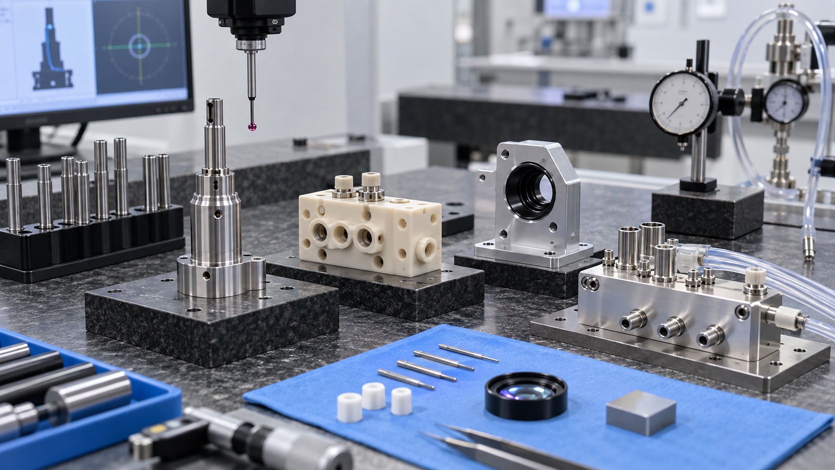
Inspection focuses on probe-axis location, bore diameter, mounting-face flatness, wash opening position, thread quality, seal grooves, edge condition and visible surface defects. CMM and optical tools can verify geometric relationships and small intersections. A borescope may be useful where direct viewing is limited. The acceptance plan should define what constitutes a removable burr, stain, embedded particle or unacceptable scratch. Mechanical inspection supports cleanability, but actual carryover and cleaning effectiveness must be tested by the instrument manufacturer with the defined fluids and cycle.
Passivate, clean and protect
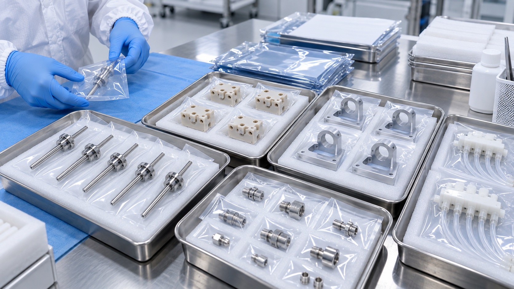
When passivation or electropolishing is specified, pre-treatment cleanliness and post-treatment inspection are part of the route. Critical fits, threads and sealing features should be rechecked after finishing. Cleaning removes cutting fluid, chips, abrasive residue and loose particles from bores and channels. Drying must not leave visible residue. Parts should be separated so polished or sealing surfaces do not rub. Packaging can be clean and traceable, but should not be described as sterile unless a validated sterile process is included in the order.
Prepare a complete RFQ
A useful RFQ includes released 2D and 3D data, exact materials, fluid-contact identification, cleaning and finish requirements, prototype and production quantities, critical datum relationships and inspection records. Add probe and fitting specifications, mating geometry, assembly torque, acceptable edge conditions and customer-supplied gauges. State whether the supplier delivers bare parts, installed bushings, fluid-block subassemblies or leak-tested assemblies. Clear scope prevents device-level analytical claims from being confused with component manufacturing evidence.
FAQ
Can component machining validate analyzer carryover?
No. Carryover depends on the complete fluid path, wash chemistry, software cycle and instrument validation. Machining supports the specified geometry and surface condition.
Which dimensions control probe alignment?
Mounting-face flatness, guide-bore position, bore straightness, perpendicularity, clamp-seat geometry and wash-opening location are common controls.
Why is 316L often considered?
It can provide corrosion resistance and stable small features, but the device designer must approve the grade for reagent, cleaning and mechanical conditions.
Should a split clamp be measured tightened?
The drawing should define the inspection state. Both free-state geometry and the specified assembled condition may be relevant.
How are hidden burrs checked?
Controlled deburring is followed by optical inspection or borescope examination where direct access is limited.
What should be sent for quotation?
Send drawings, models, materials, wetted-surface identification, cleaning, finish, quantities, datums, mating details and inspection requirements.