
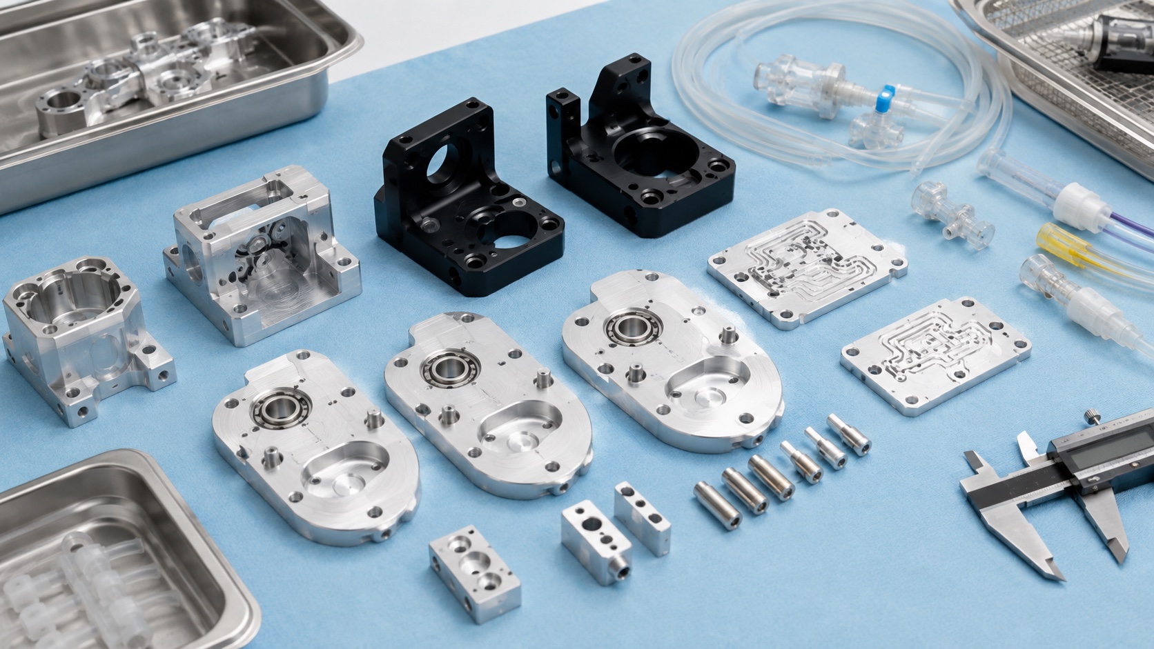
CNC Machining Peristaltic Infusion Pump Roller Mechanisms: Occlusion Gap, Alignment and Wear Control
Why the roller mechanism is critical
In a peristaltic infusion pump, the roller mechanism repeatedly compresses flexible tubing against a platen. The machined carrier, roller shafts, bearing seats and mounting features influence how uniformly that motion is transferred. Small position or runout errors can change local tube compression, noise and wear. The machining supplier produces the mechanical parts to the released design, but does not establish flow accuracy, alarm performance or clinical suitability. Those outcomes depend on the complete pump, tubing set, software and validation controlled by the medical device manufacturer.

Map the functional stack
The manufacturing review should trace the stack from motor and gearbox through the carrier to roller, tubing and platen. Identify the bearing or bushing surfaces, shaft axes, carrier mounting face and the feature that clocks the assembly. The drawing should define the nominal roller path and which dimensions contribute to the designed occlusion gap. Tolerances cannot be selected from the carrier alone because tubing wall thickness, roller diameter, platen position, bearing clearance and housing deflection all contribute to the final condition.
Select materials for load and cleaning
Aluminum can reduce rotating mass and machine efficiently for a carrier, while stainless shafts or approved bearing materials may handle repeated contact. Exact alloy, temper and finish must come from the device design. Cleaning agents, expected cycles, galvanic interfaces and wear debris should be reviewed before material release. Material certificates and lot identity support traceability. A convenient alloy substitution can change stiffness, coating response or press-fit behavior, so substitutions require documented customer approval.
Create a common datum system
A stable datum scheme normally begins with the carrier mounting face, central drive bore and a clocking feature. Roller shaft holes should be positioned from that system rather than chained from one hole to the next. Chained dimensions can accumulate pitch error around the carrier. The datum surfaces need to remain accessible for machining and CMM inspection. If the carrier mounts to a molded housing, the customer should define the functional contact pads and the condition used for assembly verification.
Machine the carrier without distortion
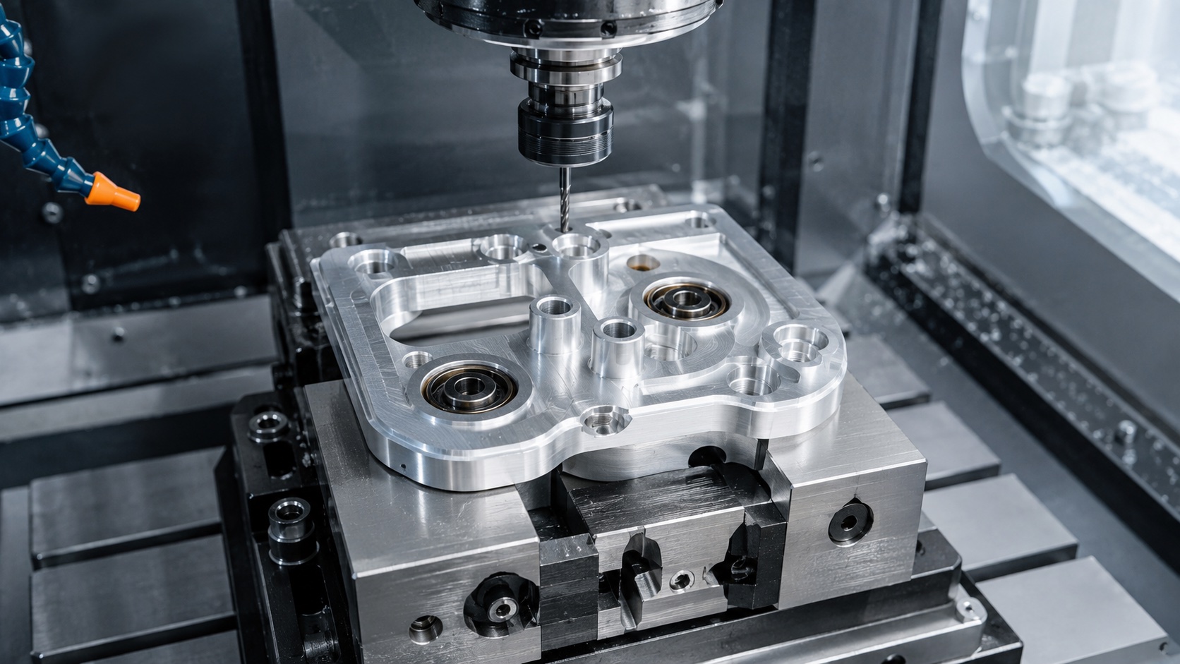
Thin webs between roller stations can move under clamp force or after material removal. A staged process roughs pockets symmetrically, leaves stock near bearing seats and mounting faces, then finishes critical bores in a supported setup. Sharp tools and controlled exits limit burrs around small holes. The fixture should distribute load across rigid areas and avoid clamping directly over flexible arms. Final inspection after unclamping is important because a bore pattern that measures correctly in the fixture may move when the part is released.
Control shafts, bores and bearings
Roller performance depends on bore diameter, axis position, perpendicularity, shaft finish and the selected bearing or bushing fit. Too much interference may distort a miniature bearing; too little can allow movement or fretting. The drawing should state whether bore dimensions apply before or after anodizing and identify masked zones. Shaft shoulders need consistent axial location, and thread or retaining-ring features must not leave burrs that interfere with assembly. Approved gauges and trial components can complement dimensional measurement.
Inspect contributors to the roller path
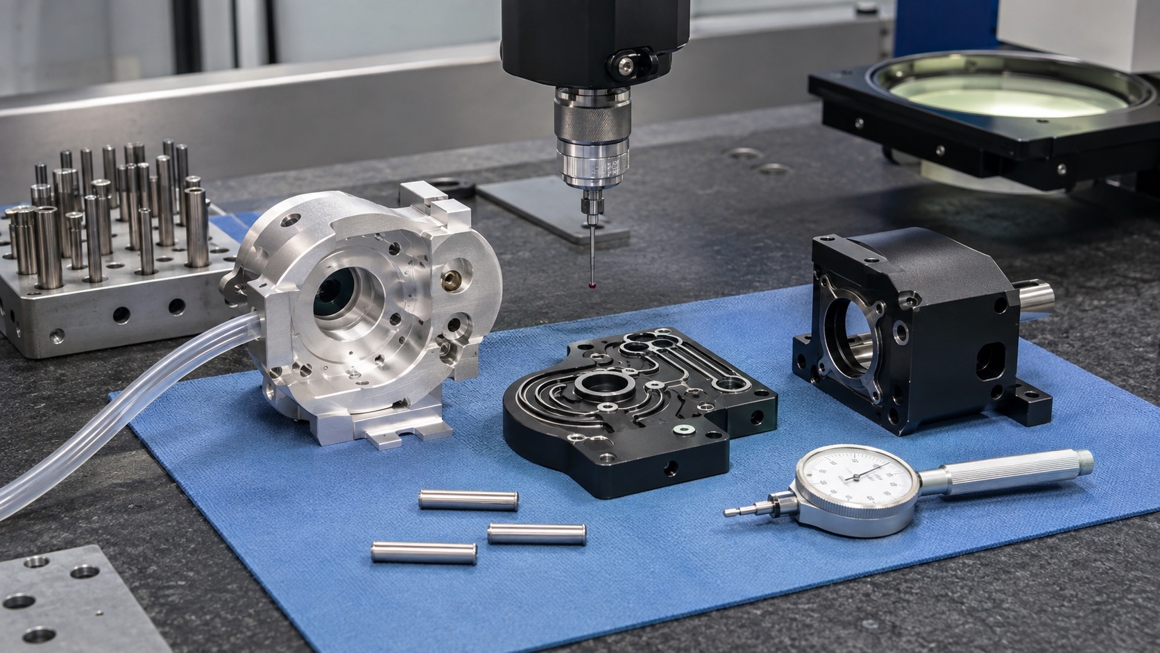
Inspection should cover mounting-face flatness, drive-bore location, roller-station pitch, bore perpendicularity, shaft diameter, roller runout and carrier thickness. CMM inspection confirms geometric relationships, while optical tools help small edges and bearing seats. A functional gauge may simulate the drive and platen references, but it must be approved by the device owner. Record measurement temperature, fixture state, tool revision and material lot. Do not infer delivered flow accuracy from component dimensions alone.
Manage finish, cleaning and packaging
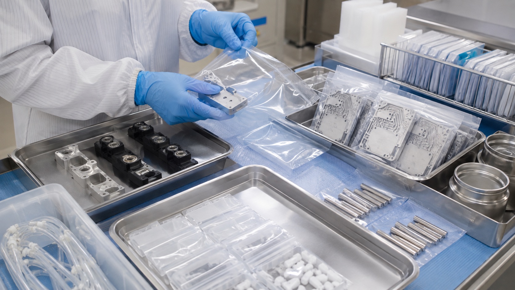
Anodizing or passivation can protect parts, but finish buildup affects bearing fits, shafts and electrical grounding points. Masking and post-finish acceptance must be defined before production. After machining and finishing, remove chips, abrasive residue and loose coating from pockets and bores. Protect precision shafts and bearing seats in separated trays or sleeves. Packaging can be clean and traceable without being described as sterile. Labels should identify part number, revision, lot, quantity and inspection status.
Build a complete RFQ
A useful RFQ includes released drawings and models, exact materials, finishes, tubing and platen interface information, prototype and production quantities, bearing specifications, critical tolerances and inspection expectations. Add cleaning requirements, marking, traceability and any customer-supplied gauges or mating components. State whether the supplier is responsible for bare parts, installed bearings, subassembly or functional testing. These inputs allow a realistic quotation without transferring device-level performance assumptions to the machine shop.
FAQ
Can the roller carrier alone determine infusion accuracy?
No. Flow accuracy depends on the complete mechanism, tubing, platen, drive control, calibration and device validation.
Which dimensions affect the roller path?
Mounting-face flatness, drive-bore location, roller-shaft pitch, bore perpendicularity, shaft diameter and roller runout are common contributors.
Why avoid chained hole dimensions?
Chained dimensions can accumulate position error around multiple roller stations; a common datum system controls the full pattern more clearly.
Should bearing bores be measured after anodizing?
Yes when coating affects the fit. The drawing should define masking, pre-finish allowance and the required post-finish acceptance.
What inspection methods are useful?
CMM, optical measurement, bore gauges, shaft micrometers, runout checks and customer-approved functional gauges can be combined.
What belongs in the RFQ?
Send drawings, models, materials, finish, bearing and tubing interfaces, quantities, tolerances, inspection, cleaning and traceability requirements.