
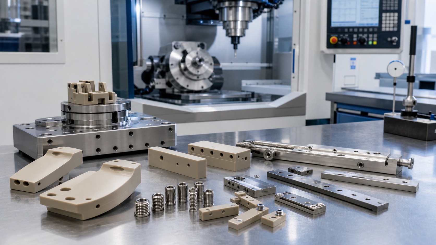
CNC Machining MRI Patient-Positioning Fixtures: Material, Datum and Artifact Control
Why MRI fixtures need a dedicated review
Patient-positioning fixtures used around MRI systems locate pads, coils, sensors and accessory assemblies while remaining easy to clean and repeatable to set up. Their geometry may appear simple, but material behavior, hidden metal, sharp edges and accumulated alignment error can affect workflow and image quality. The machining supplier should treat MRI compatibility as a device-level requirement defined by the customer. A machined polymer part cannot be declared MR Safe or MR Conditional from appearance alone; the complete assembly, environment and labeling must be assessed by the medical equipment manufacturer.

Translate clinical use into mechanical requirements
The design review begins with where the fixture sits relative to the patient, bore, coil and imaging region. Contact surfaces may need generous radii, controlled texture and resistance to repeated cleaning. Locating faces and pin holes must return the accessory to the same position without requiring excessive force. If the fixture carries a coil or calibration target, the drawing should identify the features that control its centerline and orientation. Load, cleaning chemistry, expected service life and allowed deflection should be supplied with the RFQ rather than inferred by the machine shop.
Select materials with evidence
PEEK is often considered for imaging fixtures because it is strong, machinable and electrically insulating, but grade, filler and certification matter. Glass- or carbon-filled polymers can behave differently during machining and may not suit the intended imaging environment. Other polymers such as acetal may be useful for less demanding components, while titanium or selected nonferromagnetic alloys may be used only when the device design permits them. Material selection must account for image artifact, cleaning exposure, mechanical load, flammability and regulatory documentation. Keep the exact material lot linked to each production batch.
Create a measurable datum system
A positioning block usually combines a mounting face, side stop, pin bores, slots and a shaped patient- or coil-facing surface. These features must share a clear primary, secondary and tertiary datum system. Avoid using a free-form contour as the only inspection reference when accessible pads can provide a more stable setup. The same datums should be available during machining, CMM inspection and assembly verification. If mating rails or pins are customer supplied, define their nominal size, fit and wear allowance so the fixture does not become loose or difficult to install after repeated use.
Machine PEEK without losing geometry
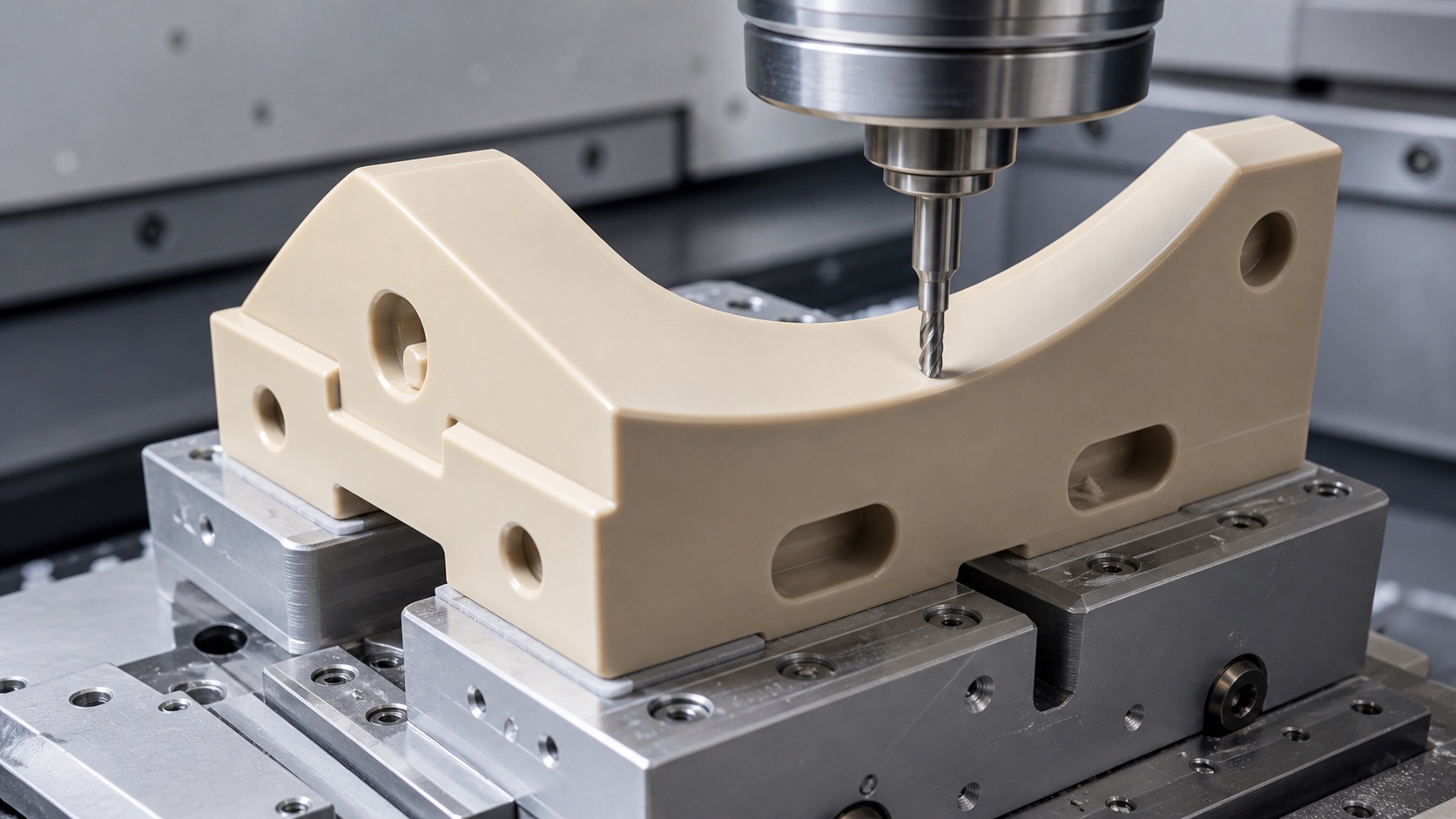
PEEK can move as internal stress is released and heat builds at the cutting edge. A robust route uses sharp tools, controlled engagement and staged roughing before critical faces are finished. Fixturing should support the blank without crushing it or imprinting cosmetic surfaces. Thin ribs, deep pockets and narrow slots need conservative tool paths and adequate chip removal. Final dimensions should be checked after the part has returned to a stable temperature. Burrs and feathered edges require controlled removal because aggressive polishing can change locating geometry or produce an uneven patient-contact radius.
Control inserts and fasteners
Threaded inserts, bushings and fasteners can simplify service, but they introduce material and alignment questions. The drawing should state insert alloy, installation method, torque and whether adhesive is allowed. Pressing an insert into a thin polymer boss can create cracks or local distortion. Metallic hardware must be reviewed within the customer's MRI safety process; the shop should not substitute a convenient fastener grade. Where removable hardware is used, poka-yoke features and visual identification can reduce assembly mistakes while lot records preserve traceability.
Inspect alignment and surface condition
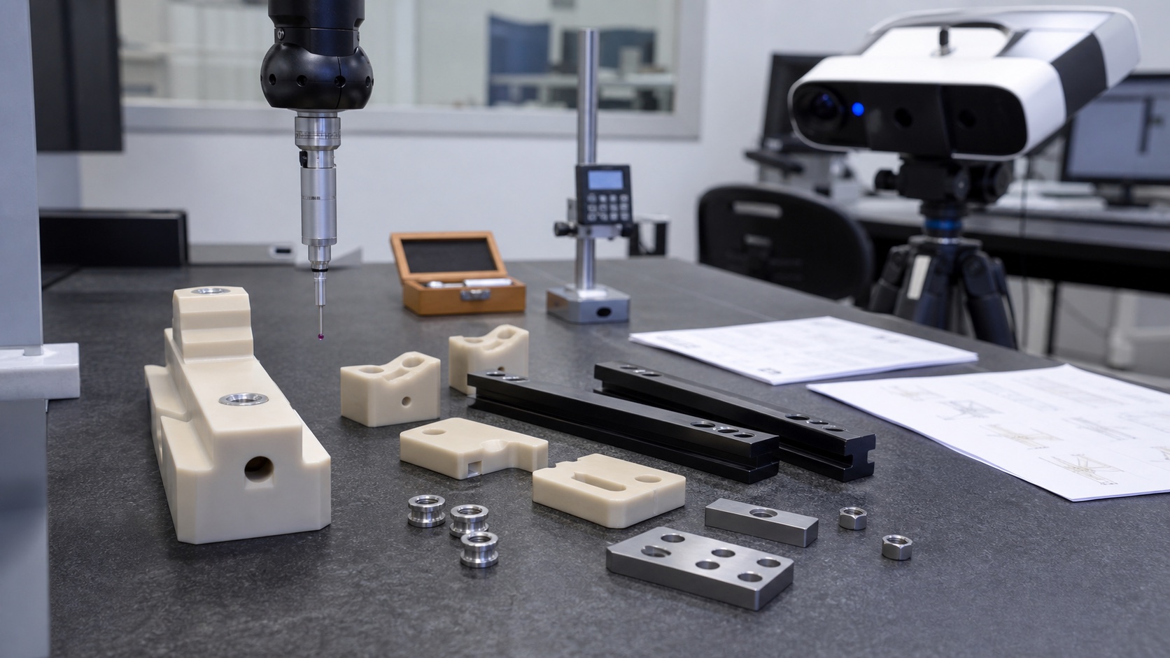
Inspection should cover mounting-face flatness, perpendicularity of stops, pin-bore position, slot width, profile of the supported surface and edge condition. A CMM or optical system can establish relationships between datums, while functional gauges may confirm mating behavior. Record the inspection temperature for tight polymer tolerances. Visual checks should look for cracks, embedded chips, raised burrs and scratches in cleanable areas. If artifact testing or scanner compatibility testing is required, the customer must define the complete assembly, sequence and acceptance criteria.
Clean and package for controlled delivery
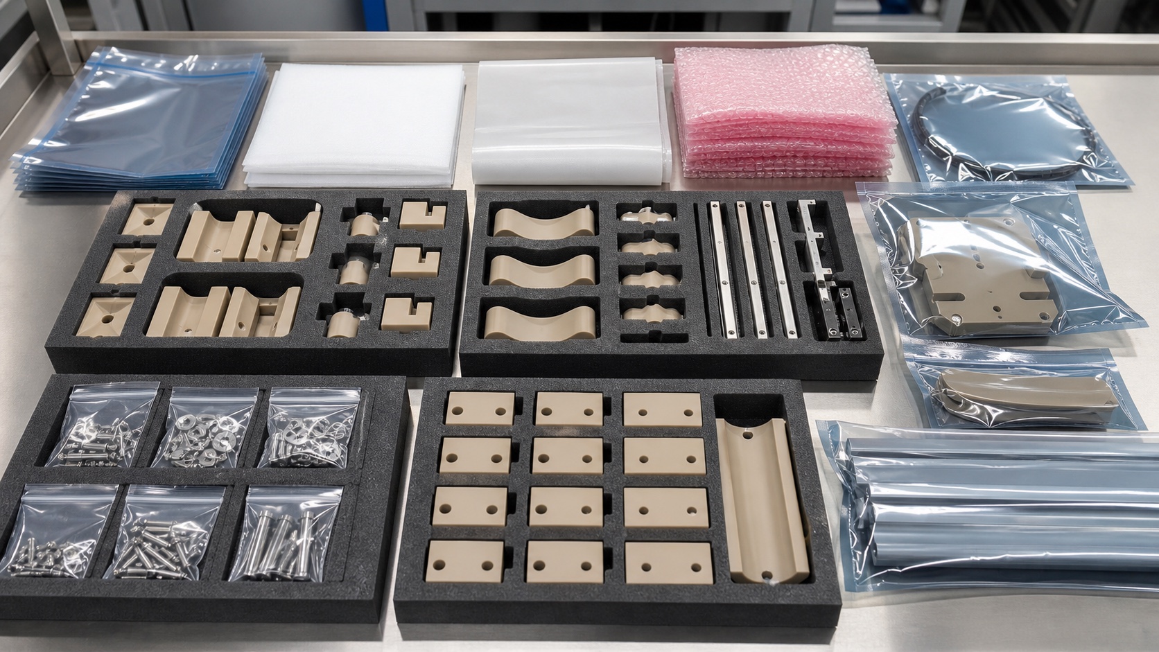
Machined parts should be cleaned with a process compatible with the polymer and specified medical equipment use. Remove cutting fluid, loose chips and polishing residue from blind holes and slots. Protect precision faces and patient-contact surfaces with separated trays or sleeves; do not let hard inserts rub neighboring parts. Packaging can be described as clean and traceable, but not sterile unless a validated sterile process is included. Labels should connect part number, revision, material lot, inspection status and quantity to the shipment records.
Build a complete RFQ package
A useful RFQ includes released 2D and 3D data, exact material grade, MRI-related material restrictions, expected loads, cleaning agents, annual quantity, prototype batch size and critical datum relationships. Add insert specifications, cosmetic zones, inspection method, documentation needs and any mating parts available for fit checks. State whether the supplier is expected to provide only machined components or also assembly and functional gauging. Clear inputs allow the manufacturing team to quote tooling, inspection and traceability effort without making unsupported assumptions about the medical system.
FAQ
Can a machine shop certify a PEEK part as MR Safe?
No. MRI safety classification belongs to the complete device and its defined use environment. The shop can provide material and manufacturing records for the customer's assessment.
Why is PEEK used for positioning fixtures?
It can provide strength, electrical insulation and good machinability, but the exact grade and its imaging, cleaning and mechanical suitability must be approved by the device designer.
Which dimensions are normally critical?
Mounting-face flatness, stop perpendicularity, pin and slot position, supported-surface profile and the relationship between coil or accessory centerlines are common critical features.
How is PEEK deformation reduced?
Use stable stock, staged roughing, sharp tools, controlled heat input, supportive fixturing and final inspection after the part reaches a stable temperature.
Can metal inserts be added?
Yes when the released design specifies them, but alloy, installation, torque and MRI safety implications must be controlled by the equipment manufacturer.
What information should accompany an RFQ?
Send drawings, models, material grade, MRI restrictions, loads, cleaning exposure, mating details, quantities, inspection requirements and traceability expectations.