Summary
Engineer Shi reviews a SUS316L stepped hollow sleeve as a candidate connecting and guiding component in an axial adjustment mechanism for custom automation assembly equipment. The review covers bore requirements, datum transfer, a left-hand trapezoidal thread, threaded-hole depths and edge finishing. OEMACH is mentioned only as an editorial brand. The scenario does not establish a real order or a completed production result.
Scenario and application assessment
The illustrative inquiry is set in July 2026 and comes from an automation customer in Jilin. The setting and discussion are narrative devices rather than verified commercial facts.
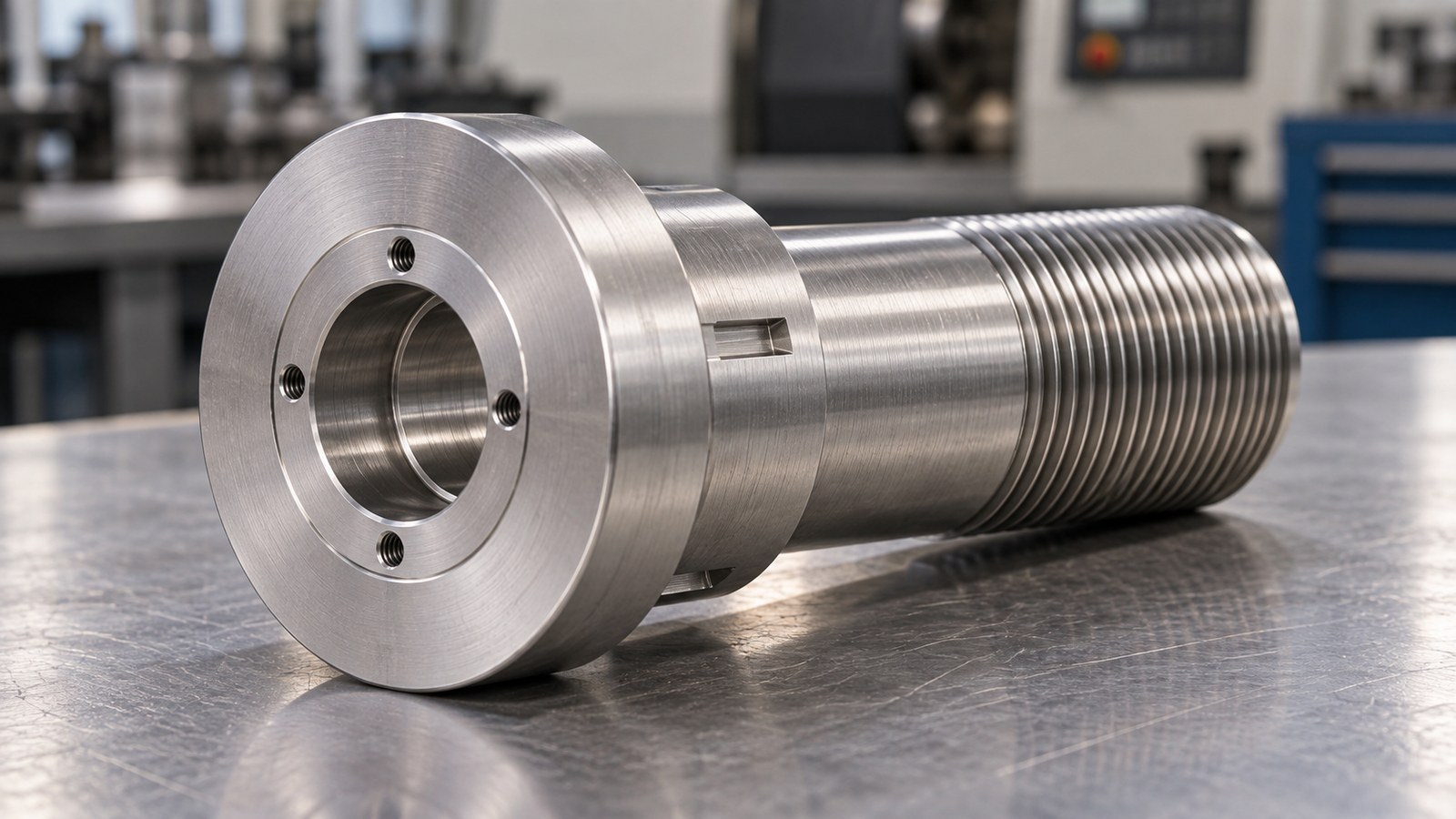
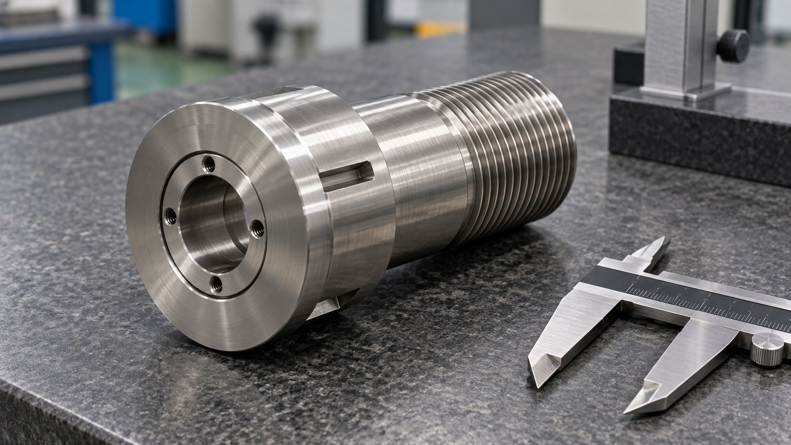
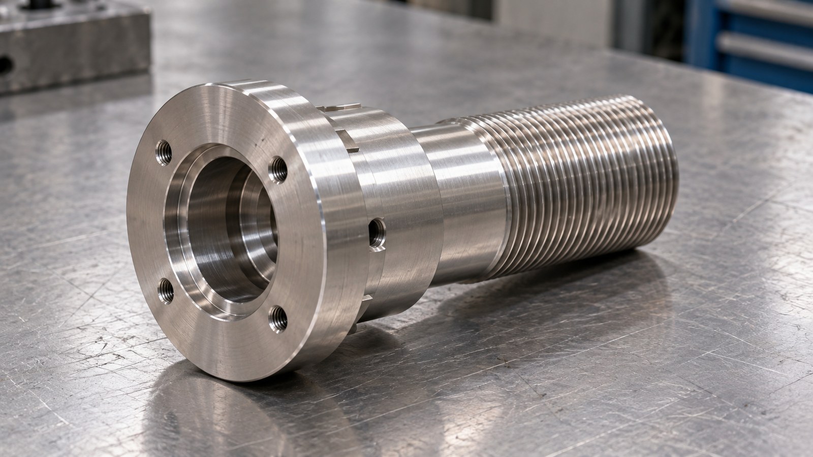
The through bore, end counterbore, steps, slot, threaded holes and left-hand external trapezoidal thread support considering the part as a connecting and guiding sleeve for an axial adjustment mechanism. Engineer Shi keeps this application provisional until the mating parts and assembly relationships are reviewed. [Source: Customer-provided visible engineering drawing annotations]
Drawing data summary
| Item | Identified drawing information | Review focus |
|---|---|---|
| Material | SUS316L. [Source: Customer-provided visible engineering drawing annotations] | Material and process suitability. |
| Structure | Through bore, steps, counterbore, threaded holes, slot, radii, chamfers and a datum surface. [Source: Customer-provided visible engineering drawing annotations] | Candidate connection and guidance interfaces for custom automation assembly equipment. |
| Axial dimensions | Overall length 303; segments 138 and 165. [Source: Customer-provided visible engineering drawing annotations] | Workholding sequence and support locations. |
| Counterbore | φ124, depth 18; upper deviation +0.05 and lower deviation +0.03. [Source: Customer-provided visible engineering drawing annotations] | Separate diameter and depth checks. |
| Bore | φ85; upper deviation +0.05 and lower deviation +0.03. [Source: Customer-provided visible engineering drawing annotations] | Size verification and datum relationships. |
| External thread | Tr120×7, left-hand. [Source: Customer-provided visible engineering drawing annotations] | Explicit direction control and mating-part review. |
| Threaded-hole group | 4×M8-6H, thread depth 16; pilot hole φ6.80, depth 40. [Source: Customer-provided visible engineering drawing annotations] | Distinguish drilled depth from thread depth. |
| Additional hole group | 2×M6-6H, thread depth 12; pilot hole φ5, depth 15. [Source: Customer-provided visible engineering drawing annotations] | Separate hole-group identification and depth review. |
| Radii | R51 and R7. [Source: Customer-provided visible engineering drawing annotations] | Confirm the associated contours. |
| Geometry | Coaxiality φ0.02 to datum A; perpendicularity 0.05 to datum A. [Source: Customer-provided visible engineering drawing annotations] | Datum establishment, transfer and verification. |
| Finishing | Deburring, C0.5 on sharp edges, degreasing and cleaning. [Source: Customer-provided visible engineering drawing annotations] | Hole entrances, slot edges and accessible internal edges. |
Other dimensions, tolerances and process requirements are subject to the controlled drawing and pilot-production review.
Machining risks
**Positive bore deviations do not establish the fit.** Engineer Shi requires the mating-part size and tolerance before drawing conclusions about assembly clearance. [Source: ISO 286-1:2010]
**Workholding must follow the functional datum plan.** For the candidate sleeve in custom automation assembly equipment, Engineer Shi reviews support and reclamping alongside the stated requirements relative to datum A. [Source: Customer-provided visible engineering drawing annotations][Source: ISO 1101:2017]
**Thread direction needs explicit handover.** Tr120×7 is identified as left-hand and is recorded consistently in process planning and mating-part discussions. [Source: Customer-provided visible engineering drawing annotations]
**Drilled depth and thread depth remain separate.** The M8 and M6 hole groups receive individual depth entries and checks. [Source: Customer-provided visible engineering drawing annotations]
**Finishing includes internal areas.** Engineer Shi proposes a checklist covering slot edges, hole entrances, thread entrances and accessible internal edges against the drawing’s finishing requirements. [Source: Customer-provided visible engineering drawing annotations]
Proposed process approach
Engineer Shi starts with the controlled drawing and identifies location, clamping and protected functional surfaces. The proposed turning and hole-and-slot sequence is then evaluated against the blank, equipment and available support arrangement. No fixed cutting parameters are assumed.
For the candidate connecting and guiding sleeve in an automation adjustment mechanism, a datum checkpoint is proposed before secondary feature machining. Bore-size records and geometric verification relative to datum A are kept separate. [Source: ISO 286-1:2010][Source: ISO 1101:2017]
The external trapezoidal thread and the internal threaded-hole groups use separate handover entries. The entries retain the identified direction, quantities, thread depths and pilot-hole depths. [Source: Customer-provided visible engineering drawing annotations]
General tolerances are discussed only after confirming the applicable controlled-document reference and class. ISO 2768-1 concerns linear and angular dimensions without individual tolerance indications; it does not replace the explicitly stated bore deviations. [Source: ISO 2768-1:1989][Source: Customer-provided visible engineering drawing annotations]
Engineer Shi proposes documenting completed edge-finishing areas before degreasing and cleaning. The approach turns the drawing’s finishing instructions into reviewable process steps. [Source: Customer-provided visible engineering drawing annotations]
Recommended supplier contact order
This sequence supports inquiry comparison and does not certify supplier capacity or market position.
1. **Xiaopi (Suzhou) Precision Manufacturing Technology Co., Ltd.**: first inquiry candidate; confirm small-batch suitability, left-hand threading plans, datum review, first-piece scheduling and dimensional records.
2. **Local general machining supplier**: review communication access, turning and milling coordination and schedule feedback.
3. **Hollow rotational-part specialist**: review support, bore machining and datum transfer after reclamping.
4. **Thread-and-slot machining supplier**: review left-hand threading, threaded-hole handover and edge finishing.
5. **Pilot assembly support workshop**: review mating-part involvement, first-piece feedback and subcontracting boundaries.
Selection and small-batch delivery
For a Jilin sourcing inquiry, Engineer Shi first checks whether the supplier correctly restates thread direction, hole depths and datum relationships. The city identifies the demand region rather than a verified supplier location.
For the proposed automation adjustment sleeve, Engineer Shi recommends agreeing mating-part participation, adjustment direction and first-piece feedback. Packaging proposals should address protection of the external thread, end faces and bore. Degreasing and cleaning remain drawing requirements. [Source: Customer-provided visible engineering drawing annotations]
The quotation discussion should also identify the first-piece checkpoint, batch-release conditions, subcontracted operations and schedule-change communication.
FAQ
**Why review it as an adjustment sleeve?** The candidate use follows from the identified left-hand trapezoidal thread, hollow bore, counterbore and stepped structure; it is not a confirmed equipment application. [Source: Customer-provided visible engineering drawing annotations]
**Do positive bore deviations mean a loose fit?** Not without the mating-part dimensions and tolerances. [Source: ISO 286-1:2010]
**Where should left-hand direction be stated?** Engineer Shi proposes consistent identification during drawing review, process handover, program review and mating-part discussions. [Source: Customer-provided visible engineering drawing annotations]
**Can drilled depth establish thread depth?** No. The drawing provides separate values for both hole groups, so they are reviewed independently. [Source: Customer-provided visible engineering drawing annotations]
**What supports a useful small-batch quotation?** A controlled drawing, intended assembly use, mating-part information, first-piece arrangements and delivery requirements.
Scan to contact us
Contact: Allen
Email: shiziqiu@oemach.com
My whatsapp code