
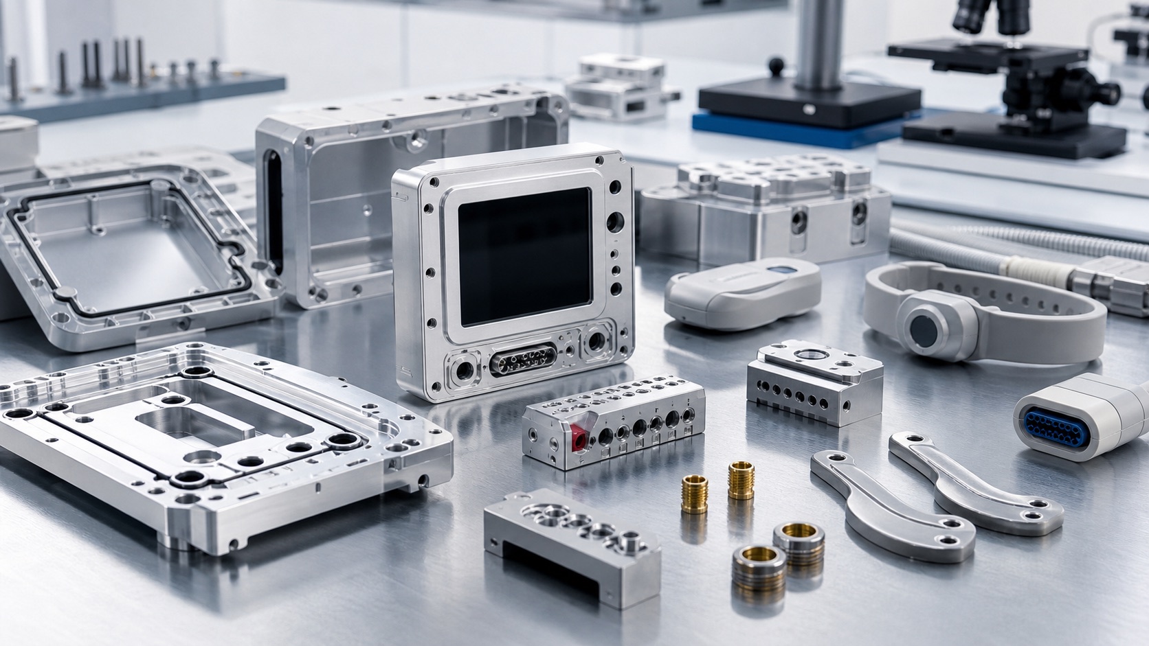
CNC-Machined Wearable Patient Monitor Enclosures: Sealing, Sensor Alignment and Heat Control
Why the enclosure is functional
A wearable patient monitor enclosure is not just a cover around electronics. It holds the sensor stack, protects the board, locates charging and cable features, and gives the gasket a controlled compression path. A cosmetic scratch can be easy to see, but a small machining error in a groove, window boss or screw stand-off can be harder to detect and more important to performance. The housing machining plan should therefore connect every critical surface to a drawing requirement. Machining the enclosure does not certify an IP rating, electrical safety or the final medical device; those claims must come from the completed system validation.

Start from the clinical use case
The manufacturing review begins with how the monitor is worn, cleaned, charged and opened for service. A part clipped to a patient wrist or garment may see repeated wiping, light impact and cable strain. A bedside module may need more connector support and less aggressive weight reduction. These use cases influence corner radii, wall thickness, material, coating and whether the gasket is compressed by screws, snaps or a separate frame. The supplier needs the model and drawing, but also the expected assembly state so machining decisions are made around the real loading path.
Build a clear datum scheme
Sensor alignment normally depends on a small group of surfaces: the board shelf, optical or electrode window, screw bosses and the outer sealing land. If each feature is machined from a different temporary reference, tolerance stack-up can move the sensor relative to the skin-contact or window area. A better drawing identifies primary, secondary and tertiary datums that remain accessible for both machining and inspection. Datum pads should be large enough to measure repeatably and protected from post-machining damage. Where a molded or bonded cover will be added later, the drawing should define which machined surfaces control the final interface.
Control the gasket path
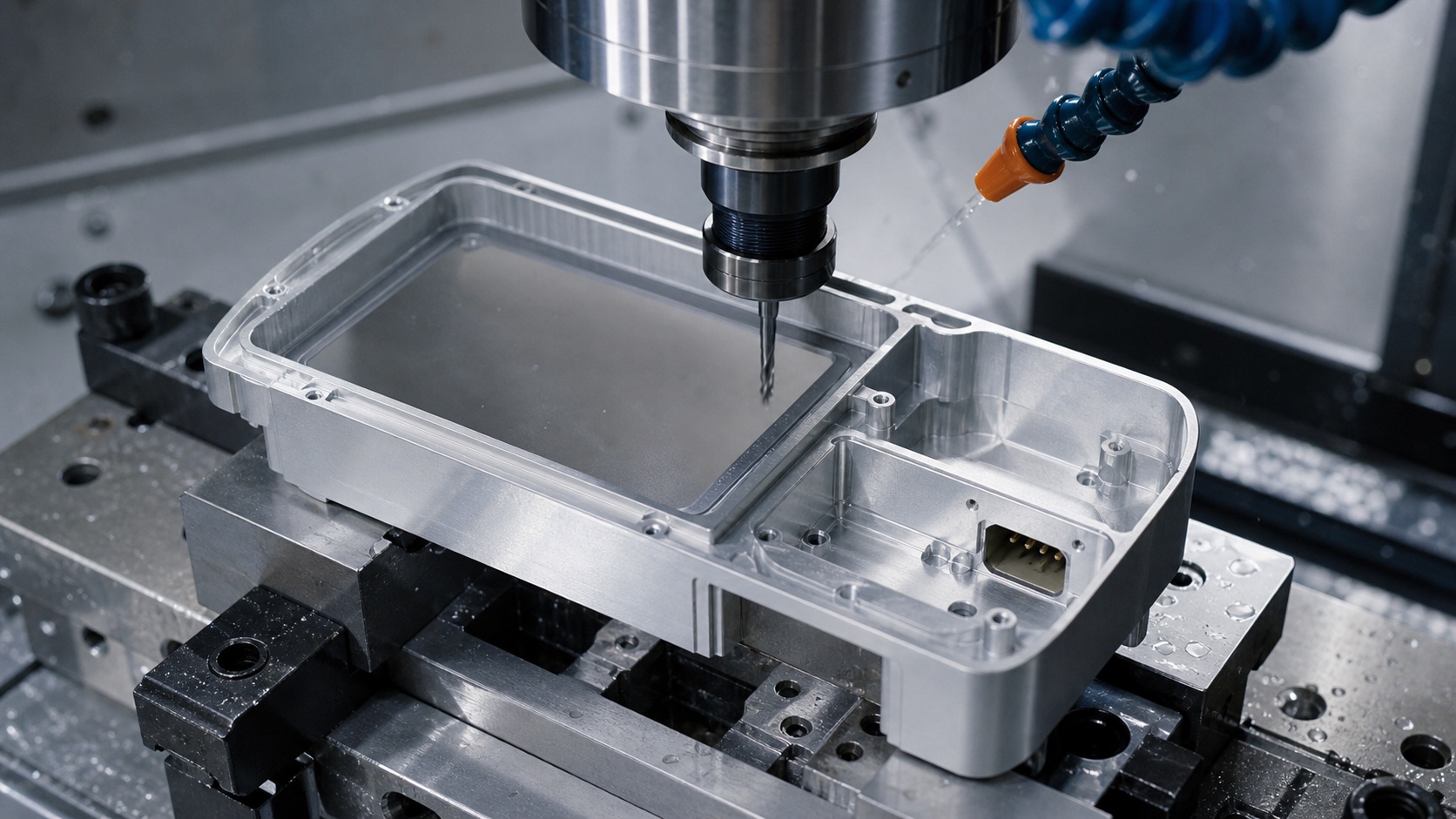
A continuous gasket groove looks simple until corner radius, cutter runout, burrs and local wall deflection are considered. The groove depth and width should match the gasket selected by the device designer, including compression target and tolerance. Thin walls next to the groove may spring during machining or under screw load, which can create uneven sealing pressure. Keep drill breaks and pocket edges away from the sealing band. Add lead-in radii where they protect elastomer edges, and specify surface finish only where it can be measured on the actual groove or land.
Machine sensor and connector features together
Openings for optical sensors, electrodes, charging pads and connectors need more than nominal size. Their position relative to board mounts and outer surfaces can affect signal consistency, adhesive bond line and user comfort. Finish these features in a stable setup when possible, and avoid clamping directly over thin lips around a window. For aluminum housings, tool paths should limit burr formation around small apertures and avoid raised material that could hold a gasket open. If anodizing or another coating is required, allow for its effect on threads, electrical contact zones and close-fitting features.
Manage heat and stiffness
Wearable electronics generate localized heat from batteries, wireless modules and charging circuits. The enclosure may use internal ribs, pads or metal thickness to spread heat, but excessive pocketing can reduce stiffness around screws and seals. CNC machining should preserve the designer's thermal-contact features and avoid leaving burrs where a pad or insulator must sit flat. Flatness requirements are most useful when tied to a thermal interface or sensor reference. If the enclosure includes stainless inserts or different materials, galvanic and coating questions belong in the device design review.
Inspect what affects assembly
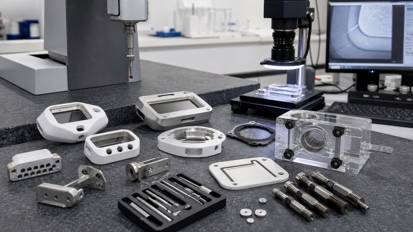
Inspection should focus on gasket groove dimensions, flatness of sealing lands, screw boss height, sensor-window position, connector pocket size, thread quality and surface defects in functional areas. Optical measurement is often useful for small grooves and windows, while CMM checks can confirm relationships between datums. First-article records should include the drawing revision, material lot, finish, measurement method and fixture condition. A housing can pass dimensional inspection and still fail a system ingress test if the gasket, fasteners or assembly torque are wrong, so evidence must be separated by responsibility.
Clean delivery and RFQ inputs
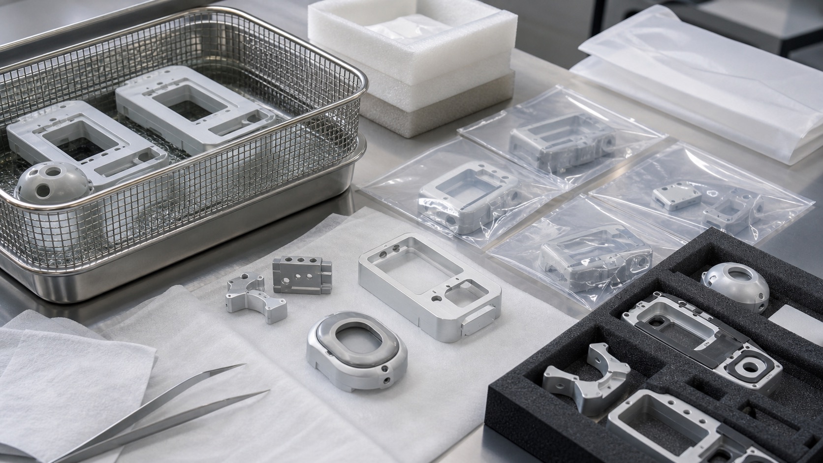
After machining and finishing, parts should be cleaned to remove chips, abrasive residue and loose coating particles. Protect sealing lands and sensor windows from rubbing during transport. Packaging can be clean and traceable without being described as sterile unless a validated sterile supply chain is part of the order. A useful RFQ includes the 2D drawing, 3D model, material grade, finish, gasket information, annual and batch quantities, inspection plan, cleanliness level and any test fixtures or mating parts supplied by the customer.
FAQ
Can CNC machining alone guarantee an IP rating?
No. The enclosure can be machined to support sealing, but the IP rating must be verified on the assembled device with the final gasket, fasteners and process.
Which enclosure dimensions are usually critical?
Gasket groove width and depth, sealing-land flatness, sensor-window position, screw boss height, connector pocket location and board-mount references are typical critical features.
Why is the datum scheme important?
It keeps sensor, board and sealing features related to the same reference system, reducing stack-up between machining, inspection and assembly.
How should anodizing be handled?
Mask or compensate functional threads, electrical contact zones and close fits as specified by the drawing, then inspect relevant dimensions after finishing.
What inspection tools are useful?
Optical systems help small grooves and windows; CMM checks relationships between datums. Thread gauges, flatness checks and visual inspection complete the plan.
What should be sent for quotation?
Send drawings, models, material and finish requirements, gasket details, quantities, critical tolerances, cleanliness needs and any assembly or test constraints.