
CNC Manufacturing Dental Guide Sleeves: Bore Fit, Concentricity and Traceability
The sleeve is one link in the guide system
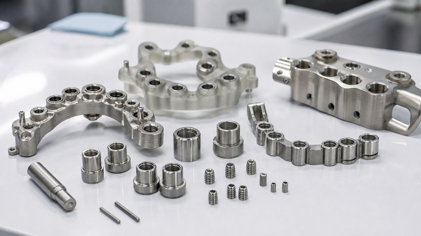
A dental surgical guide sleeve interfaces with the drill or key, the printed or machined guide body and the planned tool axis. Its dimensions cannot be reviewed in isolation. Bore size affects clearance to the instrument, the outside diameter controls retention in the guide, and the flange or shoulder determines seating depth. The device manufacturer defines the clinical plan, permitted instrument play, guide material, assembly method and validation. A CNC supplier converts those requirements into a repeatable turned component and objective inspection records. This article addresses manufacturing controls and does not claim that a generic sleeve design is suitable for a particular procedure.

Define functional datums and fits
The released drawing should identify the bore axis as a functional datum and show how the outside diameter, flange face and shoulder relate to it. Specify whether the sleeve is pressed, bonded, threaded or otherwise retained in the guide body. A nominal interference value is not enough without the guide material, hole process and tolerance. Polymer guide bodies can respond differently to insertion force and sterilization exposure than metal fixtures. Clarify the mating drill or key diameter, insertion depth and allowed axial movement. The tolerance stack should cover both sleeve manufacturing and the guide body's receiving feature, with acceptance conditions agreed before first article.
Choose material and stock condition
Titanium and stainless steel are possible materials for guide sleeves, depending on strength, wear, cleaning, imaging considerations and the device owner's design controls. The exact grade, condition and certificate requirement belong on the purchase specification. Material choice alone does not establish biocompatibility or clinical approval. Bar stock should provide enough allowance to establish concentric outside and inside features without leaving damaged surface. If passivation, anodizing or another treatment is required, the designer should account for its effect on dimensions and friction. Keep the stock lot linked to the traveler and final label whenever traceability is required.
Turn concentric features in a controlled setup
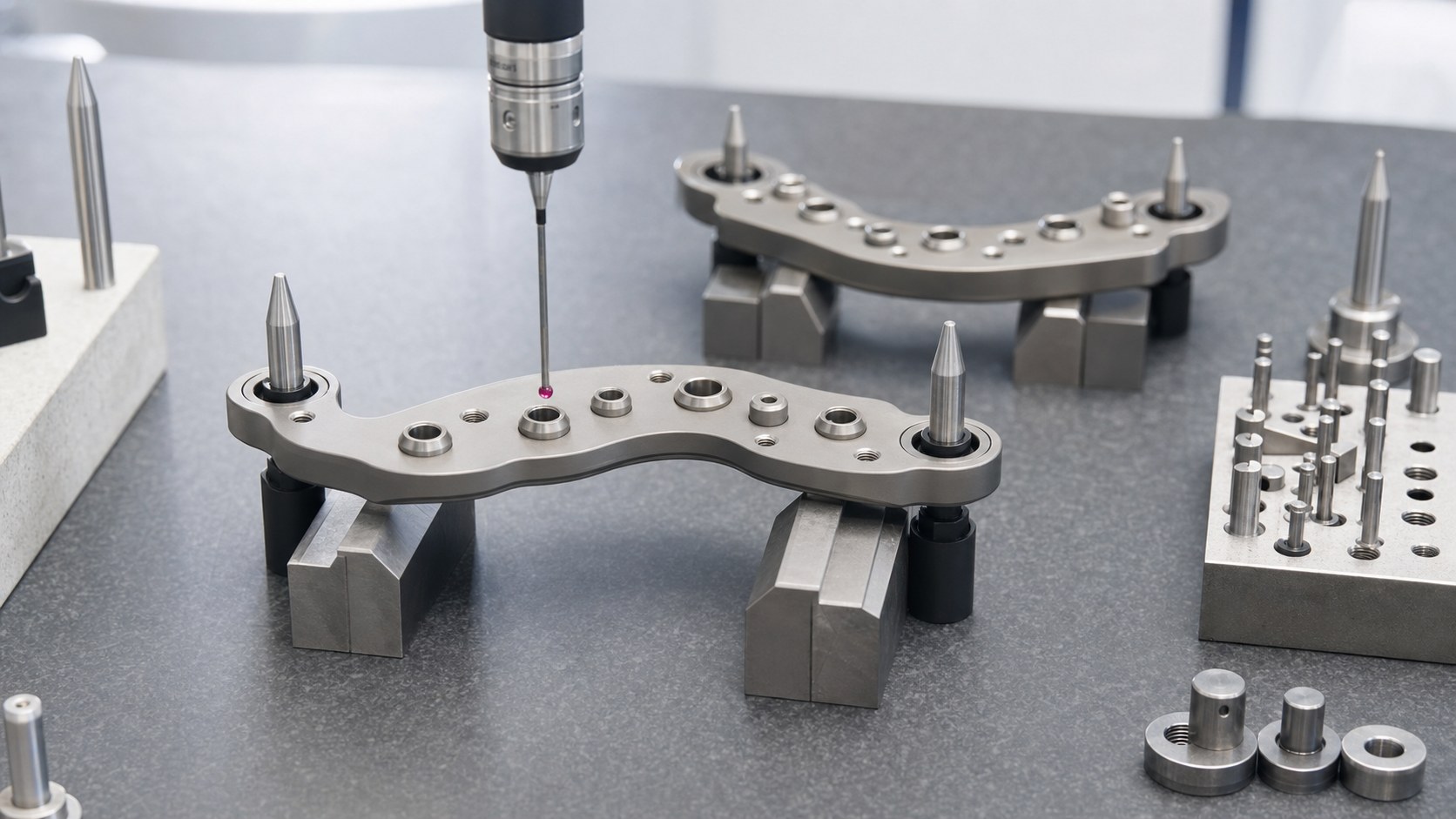
A robust process establishes the bore and the important outside diameters from a controlled axis, limiting unnecessary rechucking between the features that determine alignment. Roughing removes stock while leaving material for a stable finishing pass on the bore, shoulder and flange face. Slender sleeves may deform under excessive chuck pressure, so support and clamping force need process control. Small tools must evacuate chips without scoring the bore. If a second operation is required, locate from a finished datum and verify runout after transfer. Tool-wear limits matter because gradual bore growth can pass unnoticed across a production lot.
Control chamfers, burrs and surface condition
The drill-entry edge may need a lead-in, while the seating shoulder must remain sharp enough to locate consistently. A generic instruction to break all edges can therefore damage function. Specify chamfer or radius by location and set a maximum burr for the opposite end of the bore. Inspect for rolled metal, tool marks and particles inside the sleeve. Excessive polishing can enlarge the bore or round the flange face. If the sleeve contacts a moving instrument, the designer should define the required surface condition and test method. Cleaning removes loose contamination but cannot repair a torn edge or a tapered bore.
Inspect fit and concentricity
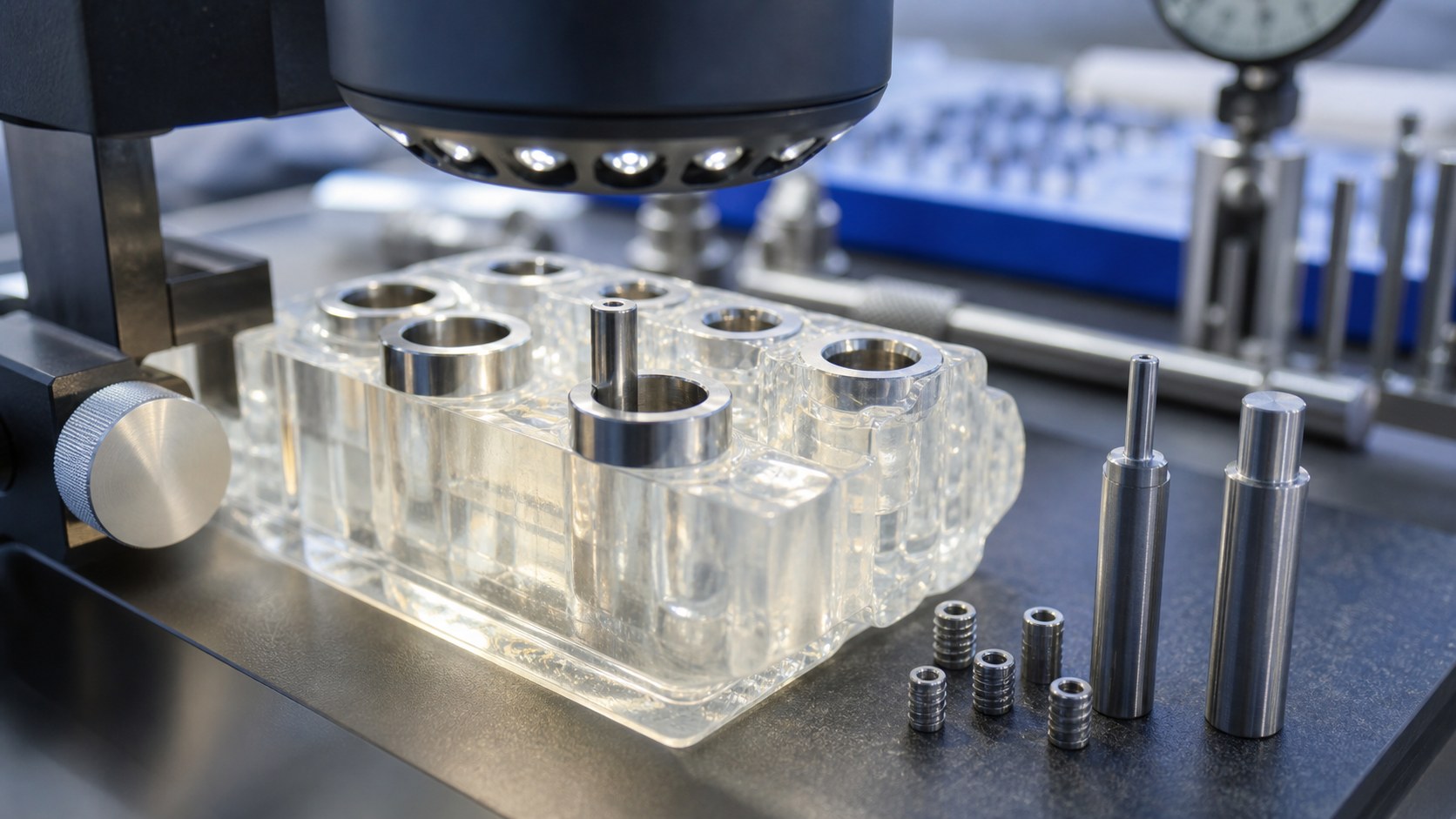
Measure bore diameter, outside diameter, flange thickness, overall length and shoulder location, then evaluate runout or concentric relationship according to the drawing's datum scheme. Air gauges, bore gauges, optical systems and coordinate measurement may each be appropriate depending on size and tolerance. A functional pin can supplement dimensional data but should not replace a defined measurement where quantitative results are required. Record the temperature and gauge condition when tolerances are tight. Trial insertion into a representative guide coupon can check assembly force and seating, but the owner must define the coupon material, hole process and acceptance range.
Clean, package and prepare the RFQ
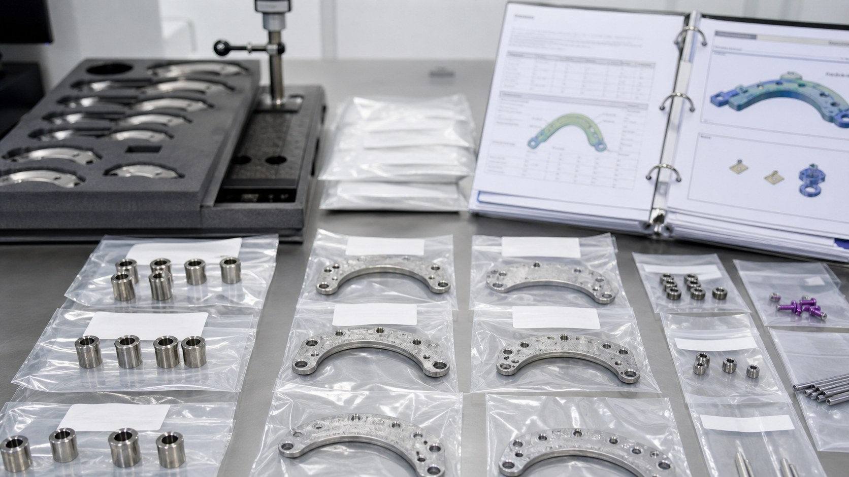
After machining and edge inspection, clean the bore and external retention surfaces to the purchase specification. Protect sleeves from metal-to-metal abrasion and prevent small parts from being mixed between lots. Packaging labels should identify part number, revision, material lot and quantity; they should not imply sterile supply unless supported by a validated process. A useful RFQ includes 2D and 3D data, guide-body material, mating instrument dimensions, retention method, quantities, critical fits, surface treatment, cleanliness level and requested inspection records. These details let the supplier quote the machining, gauges, assembly coupons and documentation actually needed.
FAQ
Why must the bore and outside diameter be related?
Their concentric relationship helps the sleeve guide the mating instrument along the axis established by the guide body.
Can one press-fit value work for every printed guide?
No. Fit depends on guide material, hole process, tolerance, insertion method and environmental exposure defined by the device owner.
Is titanium always required?
No. The designer selects material based on mechanical, cleaning, wear, imaging and validation requirements.
How is a tiny bore inspected?
Suitable methods include calibrated pins, bore or air gauges and optical measurement, selected according to the drawing tolerance.
Should all sleeve edges be rounded?
No. Entry edges may need a lead-in, while seating and locating edges may require controlled definition. The drawing should distinguish them.
What belongs in the RFQ?
Provide drawings, guide material, mating tool dimensions, retention method, quantities, critical fits, finish, cleaning and records.