
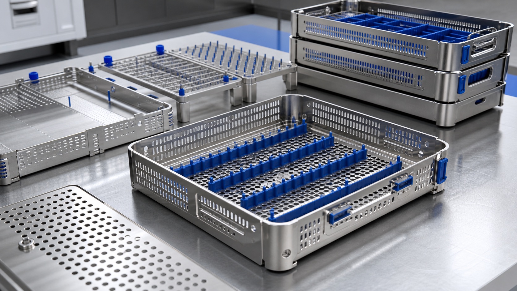
316L Surgical Instrument Tray with Removable Retention Rails: Manufacturing Case
Representative product brief
This case describes a representative reusable tray for a surgical instrument set. It is a manufacturing example rather than a claim about a named customer order or a validated sterile device. The assembly combines a perforated metal base, raised sides, removable retention rails and small locating blocks. The rails hold instruments in defined positions while allowing the owner to remove them for inspection and reprocessing. The tray is intended to fit within a larger packaging and sterilization workflow specified by the device manufacturer. Our manufacturing discussion concerns component geometry, repeatable fit, surface condition and records needed at delivery.

Start from the instrument map
Before machining, the device team supplies an instrument layout and indicates which tips, handles and joints may contact the tray. The drawing identifies envelope dimensions, rail pitch, fastener positions, stacking features and drainage openings. A stack-up review checks whether the instruments can be loaded and removed without forcing a tip against a hard edge. It also checks the clearance between a rail and the base so an inaccessible pocket is not created. The tray's expected load, permitted deflection and handling orientation are design inputs; they should be supplied rather than assumed by a CNC supplier.
316L material and traceability
The illustrative design uses 316L stainless components because of its combination of corrosion resistance and manufacturable retention details, subject to the owner's compatibility review. The purchase package should state the exact material specification and whether a certificate is required for every lot. If the base tray is formed from sheet while rails and corner blocks are machined, their material identities and finish processes must remain linked to the assembly revision. It is easier to preserve this traceability during fabrication than to reconstruct it after parts have been mixed. No material choice alone establishes that a tray is suitable for a particular cleaning cycle.
Base and rail manufacturing
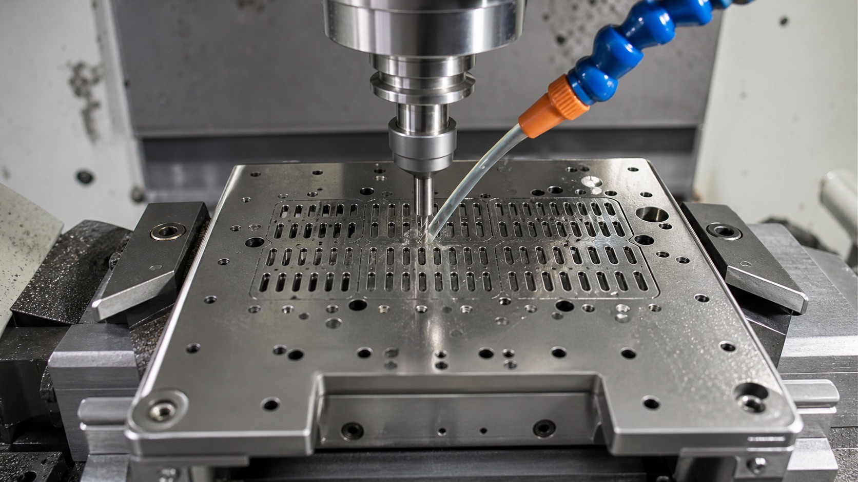
A practical route may form or cut the base tray, then CNC-finish the rail mounting features and machine the removable rails from bar stock. The machining plan establishes a stable bottom and side reference for each rail so slot and pin positions can be checked with the same datums. Roughing precedes a finishing pass on contact areas. A fixture should support the thin base without pressing visible marks into it. If the drawing includes a cover or stacking corner, trial assembly checks the full tolerance stack instead of inspecting each component in isolation. Program and fixture revisions are recorded with the first article.
Slots, perforations and edges
Drainage holes and slots must preserve strength while allowing access to surfaces. The shop controls burrs at tool exit and examines the reverse side of every representative pattern. Long slots should be machined or cut with a process that avoids distortion of adjacent walls. Retention rails need smooth lead-ins where instruments are placed; their locating shoulders need enough definition to hold position. A generic polish is not a substitute for controlled edge treatment. Before approval, compare a sample edge and surface against the drawing requirement and verify that secondary finishing has not shifted the rail fit.
Fit and inspection plan
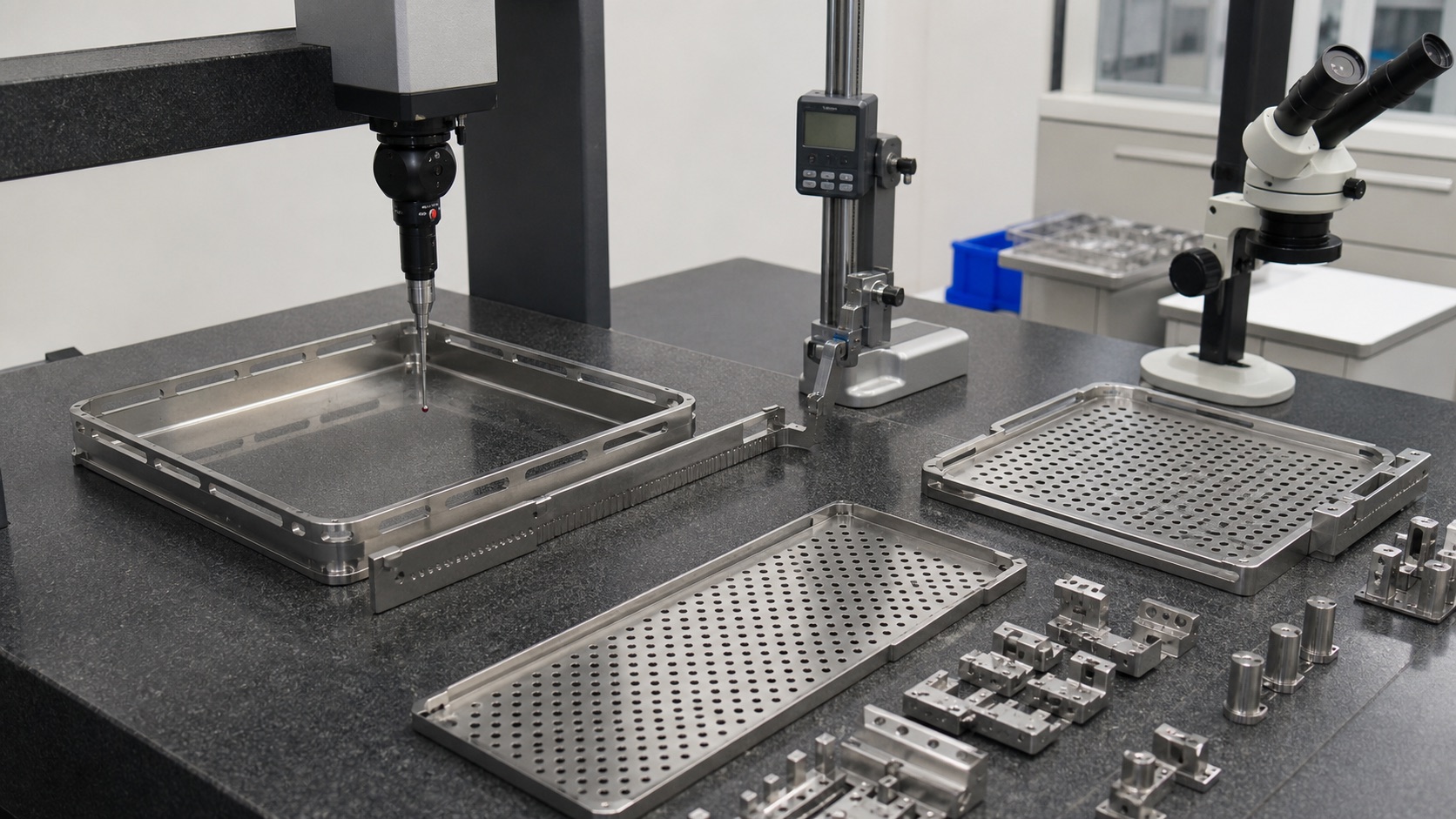
The first article can include a dimensional report for tray size, base flatness, drainage openings, rail positions, locating blocks and stack height. Assembly checks use representative instruments or agreed gauges to confirm insertion and removal clearance. Inspection photographs can document areas hidden after the rails are installed. The report should say whether measurements were taken while clamped or in the free state; thin metal components can change shape when released. Visual review includes underside edges, corners, welds if present, and any contact surface that could damage an instrument. The device owner sets any additional reprocessing validation criteria.
Cleaning and delivery preparation
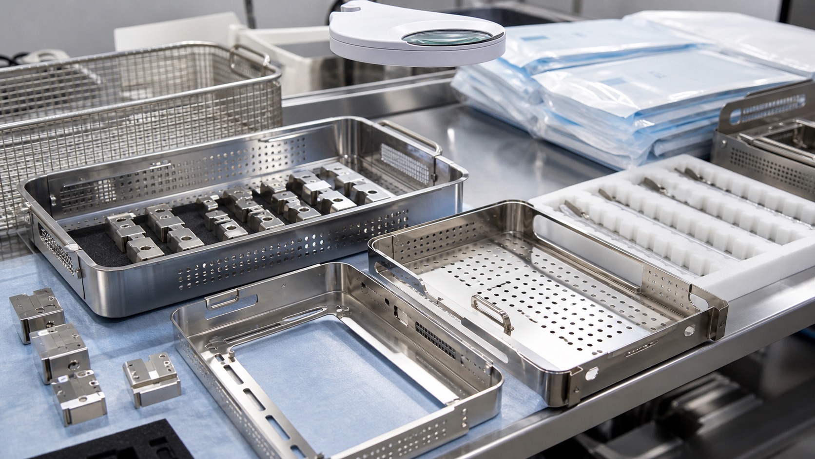
After burr removal and dimensional inspection, the parts are cleaned to the purchase specification and checked for chips, residue and loose particles. Removable rails are kept with the matching tray or labeled by revision so the assembly is not confused at receipt. Protective separators prevent metal surfaces rubbing during shipping. Packaging in the accompanying images is illustrative; it should not be described as a sterile barrier unless a validated supply chain supports that statement. Delivery documents may include material certificates, inspection results, treatment records and approved deviations. The receiving team can then connect each tray to its drawing and lot.
RFQ to repeat production
For quotation, provide the released 2D and 3D data, instrument map, assembly drawing, material and finish specification, expected load, prototype quantity, annual demand and required records. Identify which parts are removable and whether replacement rails are ordered separately. For repeat production, an approved first article, controlled work instructions and a defined inspection sampling plan support consistent assembly. If the device owner revises an instrument geometry, reassess rail spacing, contact points and drainage access before reusing the old program. This makes cost and lead-time discussions more meaningful than quoting from an image of an empty tray.
FAQ
Is this a certified sterile tray?
This is a representative manufacturing case. The device owner is responsible for validation of the complete cleaning, packaging and sterilization process.
Why are the rails removable?
Removal can improve access for inspection and reprocessing, provided the design also controls secure installation and replacement.
Can the base and rails use different processes?
Yes. A formed or cut base and CNC-machined rails can be combined if materials, finishes, fit and traceability are specified for the assembly.
Which dimensions should be inspected first?
Tray envelope, flatness, slot and hole locations, rail pitch, locating block fit and stack height are typical first-article checks.
How are burrs controlled on perforations?
Use a defined cutting sequence and secondary edge treatment, then inspect both faces of representative openings and contact edges.
What documents can be supplied?
Depending on the order: material certificates, lot and revision records, first-article measurements, surface-treatment evidence and approved deviations.