
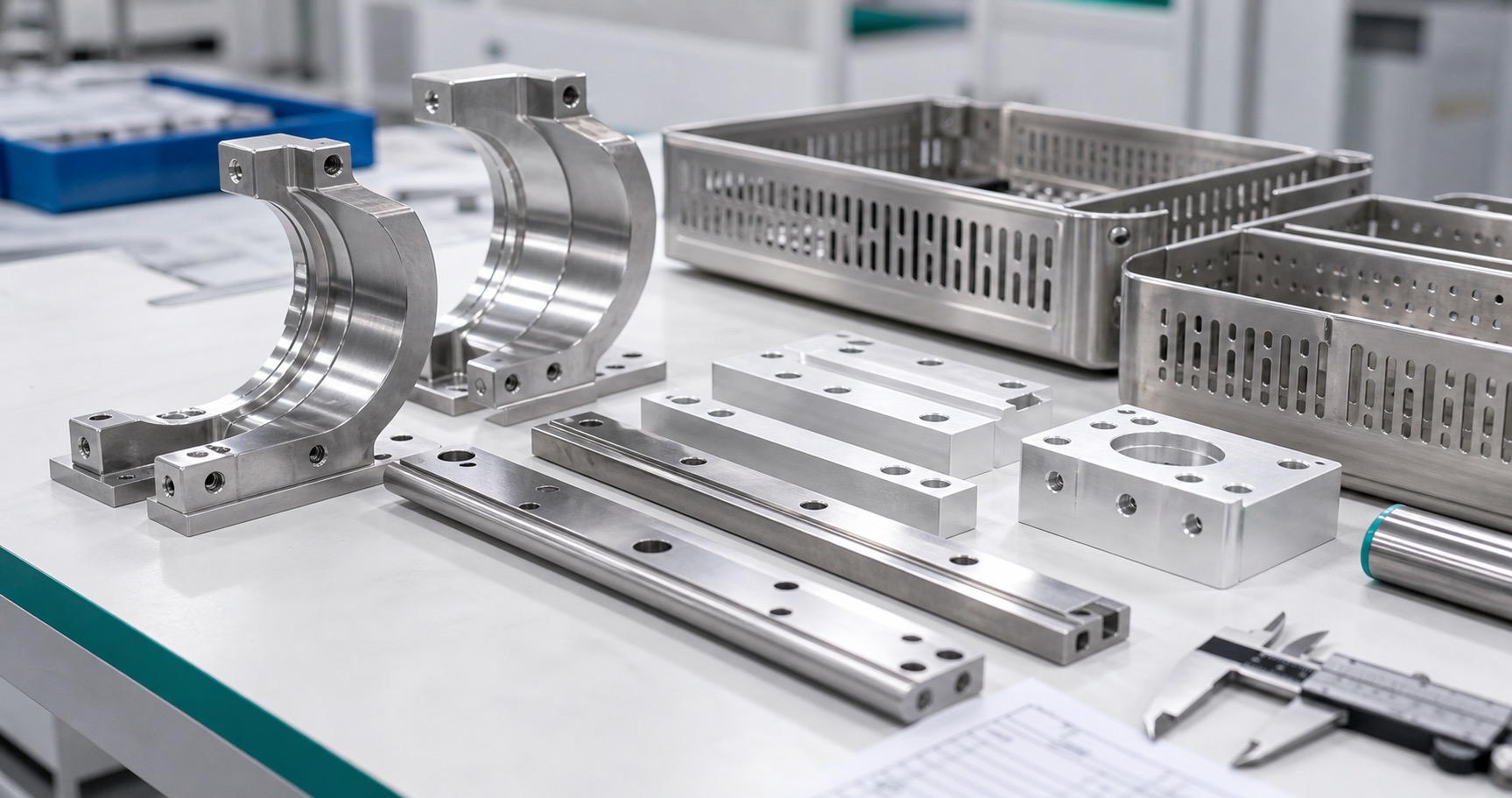
CNC Design of Reusable Surgical Instrument Trays: Drainage, Retention and Edge Control
The tray is part of a reprocessing system
A reusable surgical instrument tray carries devices through handling, cleaning, packaging and a sterilization process defined by its owner. It is not enough for a tray to hold the instruments in a photograph. Slots, feet, covers and retention points influence access to surfaces, drainage, protection during transport and the ability to inspect a set after use. The manufacturer of the complete system must validate the intended cleaning and sterilization instructions. A machining supplier can help by making the geometry repeatable, documenting material and finish, and identifying features that are difficult to clean or measure. This article focuses on those mechanical decisions rather than claiming that a tray design is automatically sterile.

Map the load and the flow path
Begin with an instrument layout showing the heaviest devices, their contact points and the way staff load and remove them. Then identify where liquid can collect when the tray is horizontal or tilted. Drainage openings should support the reprocessing strategy while leaving enough section for the expected load and handling forces. Their shape, spacing and direction matter: a long slot near a corner may weaken the side wall, whereas a narrow blind recess may trap debris. Use a drawing view to show the required orientation and the surfaces that must remain accessible for inspection. The tray owner sets the limits for allowable mass, transport and stacking; the machine shop should not infer them from the envelope dimensions alone.
Retention without hidden traps
Removable rails, pins and brackets can protect delicate instrument tips and prevent movement. The interface should still be understandable to assemble, take apart and inspect. Avoid deep blind pockets under a rail where cleaning fluid and residue could remain. Define rail contact surfaces, fastener access and a stop that prevents parts being installed in the wrong orientation. If polymer inserts are used, their material and replacement cycle belong in the device owner's specification. A tightly fitting part can be difficult to remove after repeated thermal cycles, so consider clearance, galling and assembly force together. Retention features should be checked with representative instruments, not solely against the tray's CAD model.
Choose material and finish deliberately
316L stainless steel is a common candidate for reusable medical hardware, but the exact grade and finish must follow the intended reprocessing environment. Sheet and machined components may have different surface histories, and welded areas can need separate attention. Ask for material traceability, any passivation requirement and the finish acceptance method before quoting. A polished appearance is not a substitute for a specified surface condition; a scratch under an instrument contact pad may matter more than a uniform cosmetic line elsewhere. When plastics or elastomers are added, check their compatibility with the device's cleaning agents and cycles through the owner's validation process.
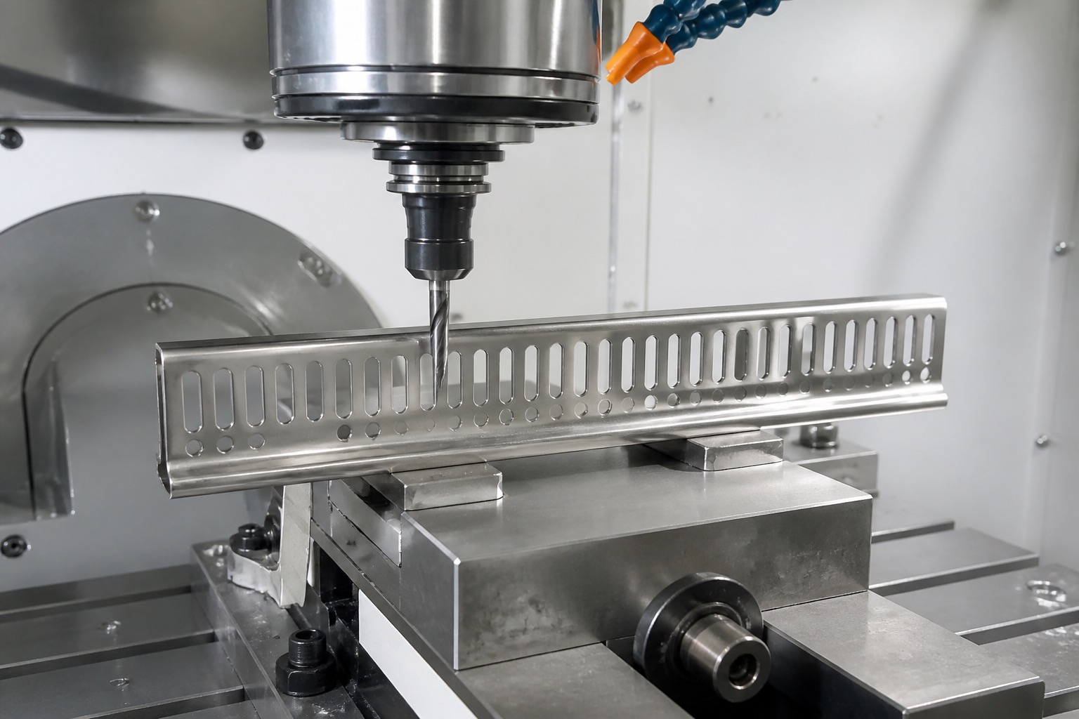
Machine holes and slots around stable datums
For machined rails, corner blocks and perforated plates, select datums that remain available after the part is cut and assembled. Rough large pockets before finish passes, then machine retention holes and slots from controlled setups. Thin sections can move after unclamping, so inspect functional spacing in the released state as well as in the fixture. Support the workpiece without marking a tray surface that will contact instruments. Long narrow slots may need a sequence that limits tool deflection, vibration and exit burrs. Where laser or sheet processes form the base tray, CNC machining can finish precisely located mounting interfaces without assuming the entire tray should be milled from solid stock.
Define an edge condition that can be verified
Every drainage hole, slot, finger opening and removable rail should have an edge condition suited to safe handling and cleaning. An instruction to remove all sharp edges is too vague for an assembly with many different functions. Specify which edges receive a radius, a chamfer or a controlled burr limit, and protect precision mating faces from excessive rounding. Inspect both sides of perforations, especially where a tool breaks through a thin wall. Loose burrs can detach during use; an overworked edge can change a rail fit or make a cover rattle. Use a representative edge sample or inspection criteria to align the drawing and manufacturing process.
Inspect the assembled system
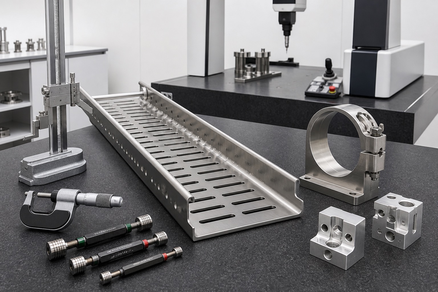
A first-article plan should measure tray envelope, flatness, slot widths, retention-hole positions, rail engagement and the clearance needed to remove instruments. Check the tray both empty and with representative load where the design calls for it. Visual inspection should include difficult corners, the underside of rails, welds and the back of perforations. Record the measurement method and the fixture condition so a later production lot can be compared. If a cleaning or sterilization validation test is required, it remains a system-level protocol from the device owner; dimensional inspection supports that work but does not replace it.
Package, document and quote
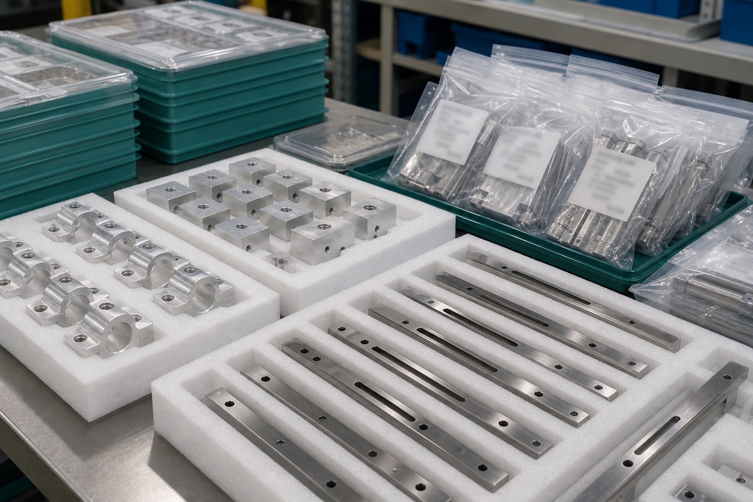
Protect finished trays and rails from metal-to-metal rubbing in transit; small edge damage can undo careful deburring. Keep removable pieces identified and paired with the tray revision. Delivery records may include material certificates, dimensional reports, surface-treatment evidence and approved deviations, according to the purchase order. For a useful RFQ, provide the instrument layout, 2D drawings, 3D model, material, expected load, finish, critical fit features, annual quantities and required documentation. State which cleaning and sterilization requirements are controlled by the device owner. Those details let a supplier review manufacturability, inspection access and assembly effort without making unsupported validation claims.
FAQ
Does a CNC-machined tray automatically meet sterilization requirements?
No. The device owner must validate the complete cleaning, packaging and sterilization process for the intended instruments. Machining controls only the specified part features.
Why are drainage slots a design concern?
Their geometry affects liquid escape, cleaning access, stiffness and the chance of burrs or trapped residue. The right pattern depends on the set and its validated process.
Should retention rails be removable?
They can be useful when removal improves inspection or cleaning, but the device owner must define assembly security, replacement and reprocessing instructions.
Is 316L the only material choice?
No. Material must be selected for load, cleaning chemistry, thermal exposure and the system's design controls. The drawing must name the required grade.
Which edges need special inspection?
Check both sides of holes and slots, rail interfaces, finger openings and contact points. Functional mating edges may require a different limit from exposed handling edges.
What should the RFQ include?
Send drawings and models, instrument layout, load and stacking information, material, finish, critical fits, quantities and required traceability and inspection records.