
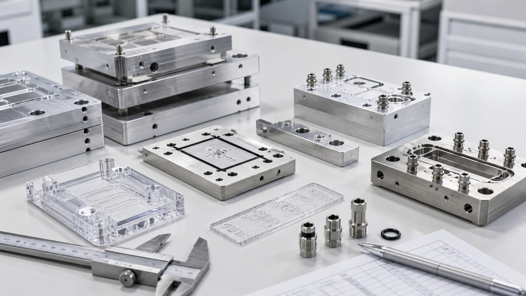
316L Medical Fluid-Control Valve Manifold: CNC Machining and Seal Inspection Case
Representative application
This case describes a representative 316L valve manifold for a medical fluid-control subsystem. It is a design and manufacturing example, not a claim about a specific customer shipment or certified device. The compact block routes fluid between an inlet, a valve interface and two outlet ports while supporting a cover seal and mounting screws. The designer controls the final fluid path, seal material, test protocol and device validation. The machine shop's role is to produce a repeatable mechanical interface and evidence that the specified features were made correctly.

Design brief and drawing inputs
The supplied package should include a released 2D drawing, a matching 3D model and a revision history. The drawing calls out the primary mounting face, a perpendicular side datum, the valve seat, port axes and the cover's seal land. It also identifies the material grade, desired surface condition and which cross-hole edges contact fluid. Before quoting, review thread callouts, drill depth, wall thickness between adjacent ports and access for deburring. Any missing leak-test values or cleaning limits must be clarified with the device owner rather than assumed.
Material and blank strategy
316L stainless stock offers corrosion resistance and enough stiffness for small threaded and sealing features, subject to the final fluid compatibility review. Start from stock with adequate machining allowance and keep lot identity with the traveler. Roughing leaves material around the cover face so the finishing pass can establish the sealing datum after the bulk of the stress has been released. If the blank is cut from plate, verify its condition and orientation before choosing a clamping face. Material certification and traceability requirements should be agreed before the first article, because they cannot be reconstructed reliably afterward.
Feature planning
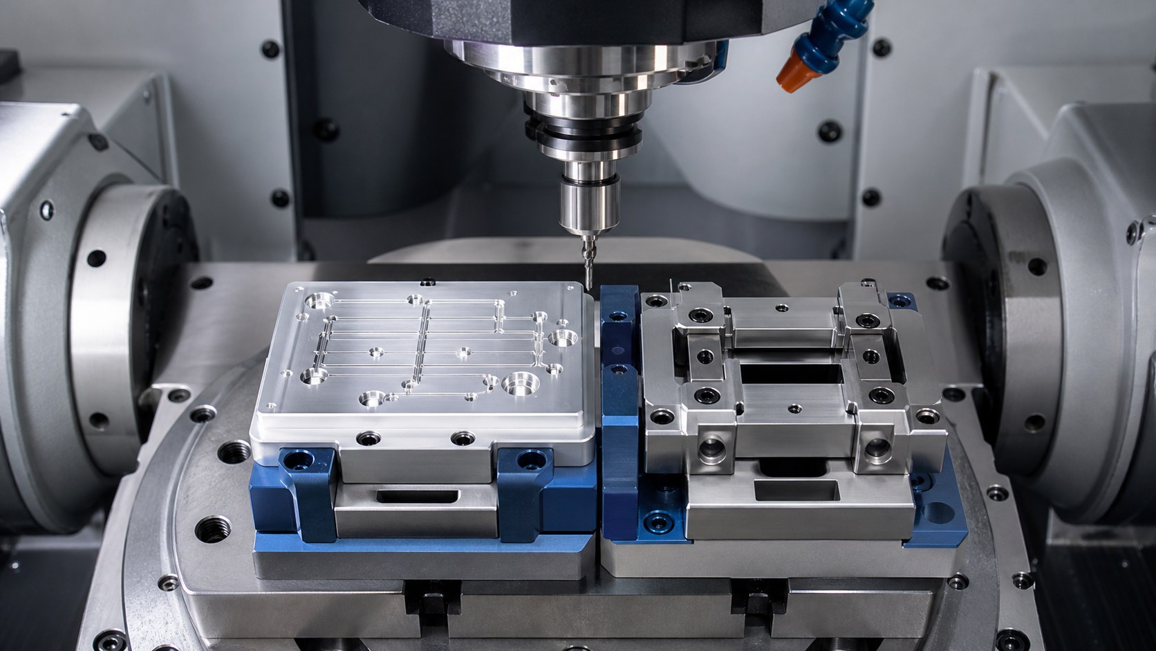
The manifold combines intersecting bores, threaded connections, a shallow seal groove and a face-milled seat. These features are not independent: moving a port can reduce wall thickness or place a bore edge under the O-ring. The CAM review therefore checks the full stack of drill tip, fitting engagement and groove geometry. A datum scheme based on accessible exterior faces allows both machining and metrology to reference the same coordinate system. Where the cover clamps the seal, the screw pattern must be reviewed for even load rather than being treated as noncritical hardware.
Machining sequence
First establish the mounting and side datums, then rough the block and create the major ports. Finish the small bores and the valve interface in a controlled setup, leaving the seal groove and adjacent land for a final stable pass. The fixture should provide enough support without masking the sealing face or distorting the block. Use tool choices and feeds suitable for 316L, monitor tool wear at the small features and clear chips from blind or intersecting passages. Record setup changes so a first-article result can be linked to the program and fixture revision.
Burr and surface control
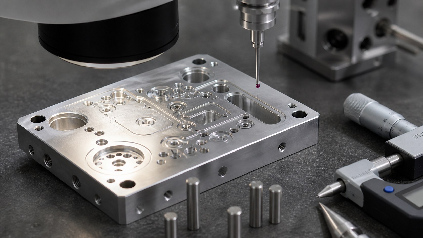
Port intersections and thread exits receive a controlled edge treatment. The purpose is to remove loose metal while preserving dimensions, not to make every edge visibly rounded. A small damaged land can create a leak route even when the rest of the block measures correctly. Inspect the seal groove with optical magnification, check the face for handling marks and verify that thread entrances will not damage a mating fitting. If passivation or another treatment is specified, recheck the relevant surfaces afterward because finishing can expose or create defects that were not visible at the machining stage.
Dimensional and functional inspection
A first-article package can include material identification, a dimensional report, groove and port measurements, surface checks and photographs of difficult intersections. The inspection plan uses the drawing datums and captures the fixture state used for measurement. A separate leak-test fixture may be appropriate, but only after the device team supplies test medium, pressure, duration, port plugging pattern and acceptance criteria. Testing the bare block and testing the assembled valve are different operations; the acceptance document should identify which one is required.
Cleaning and delivery
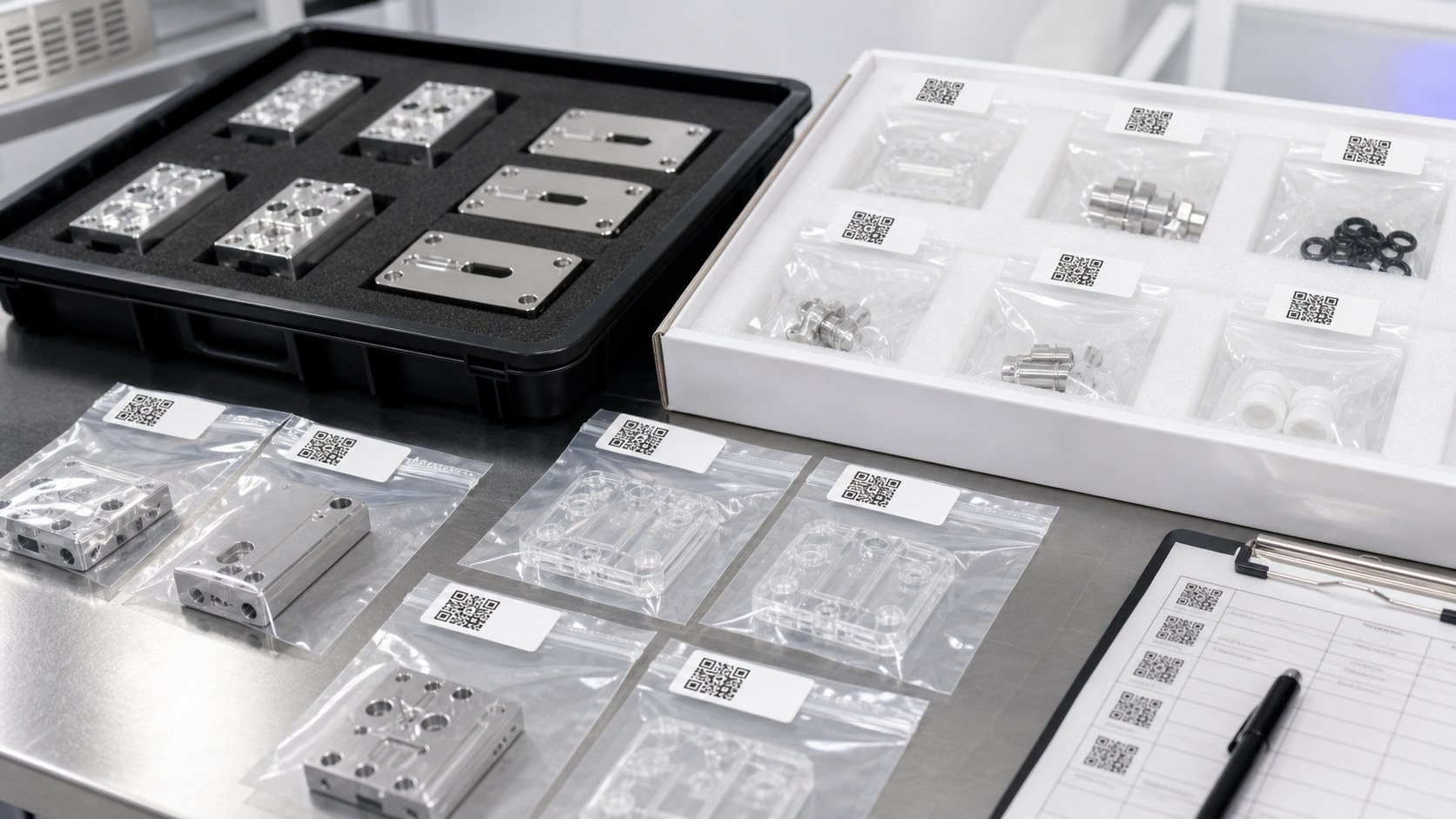
Clean intersecting passages with a process appropriate for the material and specified cleanliness level, then inspect for trapped chips and visible residue. Protect open ports, threads and the seal land from handling damage. Separate parts in trays or individual protective packaging and label the lot and drawing revision. Packaging shown in the images is illustrative and should not be described as sterile unless the validated supply chain requires and supports that claim. Delivery records can include material certificates, inspection results, deviation approvals and the agreed leak-test evidence.
RFQ and production handoff
For repeat orders, the useful handoff is a controlled drawing package, an approved first-article result and a clear list of characteristics to monitor. State prototype and production quantities separately, identify annual demand, and define whether mating seals and fittings will be available for trial assembly. Share the device's cleaning, traceability and leak-test requirements with the RFQ. This allows the shop to estimate machining time, inspection access, fixture cost and documentation effort without hiding assumptions inside a unit price.
FAQ
Is this an actual certified medical device?
This is a representative machining case. Final device certification, material compatibility and validation belong to the device manufacturer.
Why use 316L for the block?
It can offer corrosion resistance and robust small features, but the final choice depends on fluid, cleaning and sterilization compatibility specified by the device designer.
Which dimensions drive sealing?
Groove depth and width, face flatness, port location, cover screw pattern and valve-seat geometry are typical characteristics to control against the drawing.
How are intersecting passages deburred?
Use a controlled machining and secondary deburring sequence, followed by suitable optical or borescope inspection where the intersection is hard to access.
What leak-test data must the customer provide?
The device owner defines the test medium, pressure, hold time, plugged ports, assembly state and acceptance limit.
What documents can accompany the parts?
Depending on the order, material certificates, lot and revision traceability, first-article measurements, inspection records and agreed test results can be supplied.